


115
SUBMITTAL SHEETS
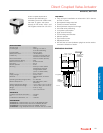
Unitary Valve Actuator
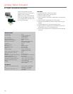
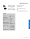
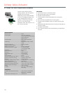
VU443, VU444; VU843; VU844
VU443, VU444; VU843; VU844
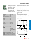
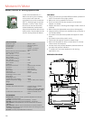
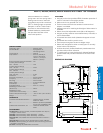
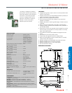
The VU844 Fan Coil Valve
Actuators are used in conjunction
with the VU52, VU53 and VU54
valves for controlling the flow of hot
or chilled water in commercial
HVAC equipment such as fan coil
units, terminal reheat coils and
convectors. These valves are
humidity resistant and are suitable
for use in condensing, non-
corrosive environments.
SPECIFICATIONS
Actuator Type .......................................Valve
Control Signal .......................................SPST
Fail Safe Mode .....................................Spring Return
Electrical Connections .........................Leads
Electrical Connection Length ............... 6 in.
Frequency ............................................60 Hz
Manual operation .................................Lever
Stroke ...................................................22 deg. (24 grad.)
Supply Voltage .....................................24V, 120V, 208V, 240V, or
277 Vac
Materials ...............................................Stainless Steel Case,
Aluminum Cover,
Nickel-plated motors available
Medium Temperature ...........................200 F (94 C)
Ambient Temperature Range ...............34 F to 125 F ambient at
200 F Fluid
(1 C to 52 C ambient at
93 C Fluid)
APPROVALS
Canadian Standards Association .........Certified C/US
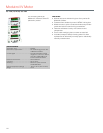
FEATURES
• Compact construction for easy installation.
• Fits under the cover of most baseboard convectors with
actuator fitted to valve body.
• One-button, quick release. Secure 3-point, metal latch to
valve body.
• Spring return operation.
• Stainless steel case and aluminum cover. Rust-proof nickel-
plated motors available.
• Line or low voltage, rust-resistant motors.
• Manual opener for installation and valve operation on power
failure.
• Valve returns to automatic position when power is restored.
• Actuator may be reinstalled or serviced without draining the
system or disassembling the valve.
• Slotted conduit hole for faster wiring.
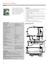
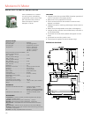
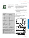
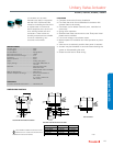
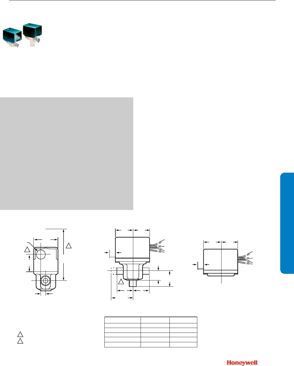
DIMENSIONS DIAGRAM
2
2
1
1
VU53 VALVE WITH VU448 ACTUATOR
VU53 AND VU54 VALVE WITH ACTUATOR
VU5 ACTUATOR
2-3/8
(60)
7/8 DIA.
(22)
1-1/2
(38)
3-3/4
(133)
15/32
(12)
3/8
(10)
1-3/4
(44)
1-3/4
(44)
A
A
B
AB
7
3/8
(10)
A
2-1/8 (54)
(INVERTED
FLARE)
1-3/4
(44)
1-3/4
(44)
B
3-WAY
7/8 (23)
2-WAY
VALVE BODY SIZE A B
1/2 IN. SWEAT 1-5/6 (33) 1-5/6 (33)
3/4 IN. SWEAT 1-3/8 (35) 1-11/16 (43)
1 IN. SWEAT 1-11/16 (43) 1-11/16 (43)
1/2 IN. NPT 1-3/8 (35) 1-5/16 (33)
3/4 IN. NPT 1-11/16 (43) 1-7/16 (37)
HEIGHT NEEDED TO REMOVE ACTUATOR OR COVER
OPENING FOR 1/2 IN. CONDUIT ON OPPOSITE SITE OF
MANUAL LEVER FOR ALL MODELS.
M18261