


255
APPENDIX
2. For hot water coil valves:
Where:
cfm = Airflow through the coil.
1.08 = A scaling constant. See Note.
TD
a
= Temperature difference of air entering and
leaving the coil.
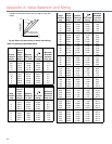
K = Value from Table 3; based on temperature
of water entering the coil (pounds per
gallon x 60 minutes per hour).
TD
w
= Temperature difference of water entering
and leaving the coil.
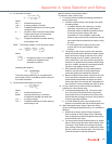
NOTE: The scaling constant 1.08 is derived as follows:
Where:
Simplifying the equation:
To find the scaling constant for air conditions other
than standard, divide 14.40 Btu by specific volume of
air at those conditions.
3. For fan system chilled water coil valves:
Where:
cfm = Airflow through the coil.
Btu/lb= Heat per pound of dry air removed.
Includes both sensible and latent heat.
113 = A scaling constant.
TD
w
= Temperature difference of water entering
and leaving the coil.
WATER VALVE PRESSURE DROP
To determine valve pressure drop:
1. For two-way valves consider the following guidelines for
valve pressure drop:
a. Include the pressure drop in the design of the water
circulating system.
— In systems with two-way valves only, it is often
necessary to provide a pump relief bypass or
some other means of differential pressure control
to limit valve pressure drops to the valve
capabilities. For control stability at light loads,
pressure drop across the fully closed valve should
not exceed triple the pressure drop used for sizing
the valve.
— To avoid high pressure drops near the pump,
reverse returns are recommended in large
systems.
b. The pressure drop across an open valve should be
about half of the pressure difference between system
supply and return, enough so that the valve, not the
friction through the coil or radiator, controls the vol-
ume of water flow or the valve pressure drop should
be equal to or greater than the pressure drop through
the coil or radiator, plus the pipe and fittings connect-
ing them to the supply and return mains.
c. Verify allowable full open and full closed pressure
drops for all proportional and two-position water
valves with appropriate manufacturer literature.
d. Make an analysis of the system at maximum and min-
imum rates of flow to determine whether or not the
pressure difference between the supply and return
mains stays within the limits that are acceptable from
the stand point of control stability and close-off rating.
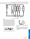
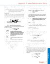
2. For two- and three-way valves consider the following
guidelines for valve pressure drop:
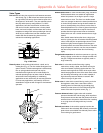
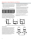
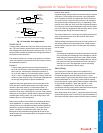
a. In load bypass applications (Fig. 13) such as radia-
tors, coils, and air conditioning units, the pressure
drop should be 50 to 70 percent of the minimum dif-
ference between the supply and return main pressure
at design operating conditions.
b. A manual balancing valve may be installed in the
bypass to equalize the load drop and the bypass drop.
3. When selecting pressure drops for three-way mixing
valves in boiler bypass applications (Fig. 13), consider the
following:
a. Determine the design pressure drop through the
boiler including all of the piping, valves, and fittings
from the bypass connection through the boiler and up
to the three-way valve input.
b. The valve pressure drop should be equal to or greater
than the drop through the boiler and the fittings. If the
valve drop is much smaller than the boiler pressure
drop at design, effective control is obtained only when
the disc is near one of the two seats. The mid-portion
of the valve lift will be relatively ineffective.
= the specific volume of air at standard
conditions of temperature and
atmospheric pressure.
Q
cfm 1.08 TD
a
××
K TD
w
×
---------------------------------------------=
1.08
0.24BTU
lbairF
-----------------------
60min
1hr
----------------
1lbair
13.35ft
3
--------------------××=
1lbair
13.35ft
3
--------------------
1.08
14 40Btumin,
Fhr13.35ft
3
-----------------------------------=
Q
cfm Btu lb⁄×
113 TD
w
×
------------------------------------=
Appendix A: Valve Selection and Sizing