


252
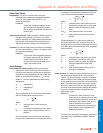
EXAMPLE:
When a valve with the stem at 30 percent of its total lift and
existing flow of 3.9 gpm (Table 2) opens an additional 10 per-
cent of its full travel, the flow measures 6.2 gpm or increases
60 percent. If the valve opens an additional 10 percent so
the stem is at 50 percent of its full travel, the flow increases
another 60 percent and is 9.9 gpm.
Table 2. Stem Position vs. Flow for Equal Percentage Valve.
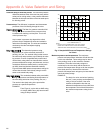
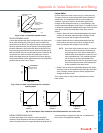
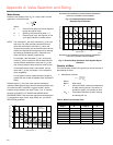
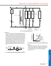
An equal percentage valve is used for proportional control in hot
water applications and is useful in control applications where
wide load variations can occur. Typically in hot water
applications, large reductions in flow through the load (e.g., coil)
cause small reductions in heat output. An equal percentage
valve is used in these applications to achieve linear control. For
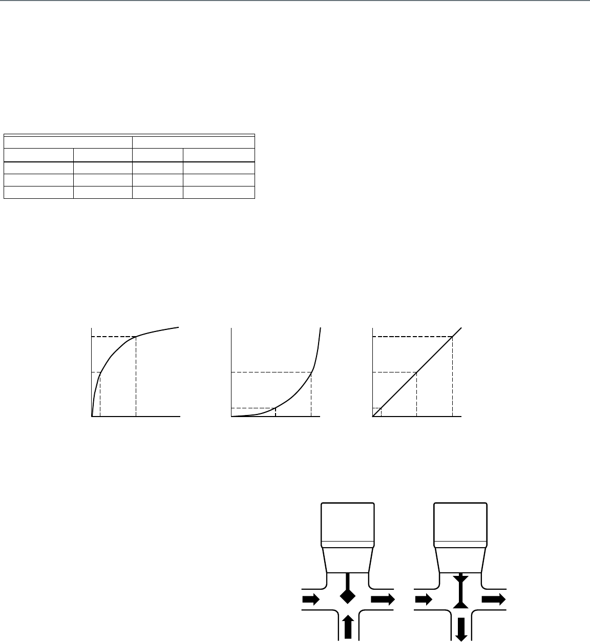
example, Figure 11 shows the heat output, flow, and stem travel
relationships for a hot water coil, with 200F, entering water and
50F entering air and an equal percentage valve, as follows:
— Graph A shows the nonlinear relationship between heat
output and flow for the hot water coil. A 50 percent reduction
in flow causes a 10 percent reduction in heat output. To
reduce the heat output by 50 percent, the flow must
decrease 90 percent.
— Graph B shows the nonlinear relationship between flow and
stem travel for the equal percentage control valve. To reduce
the flow 50 percent, the stem must close 10 percent. If the
stem closes 50 percent, the flow reduces 90 percent.
— Graph C shows the relationship between heat output and
stem travel for the combined coil and equal percentage
valve. The combined relationship is close to linear. A 10
percent reduction in heat output requires the stem to close
10 percent, a 50 percent reduction in heat output requires
the stem to close 50 percent, and a 90 percent reduction in
heat output requires the stem to close 90 percent.
The equal percentage valve compensates for the
characteristics of a hot water application to provide a control
that is close to linear.
Fig. 11. Heat Output, Flow, and Stem Travel Characteristics of an Equal Percentage Valve.
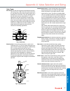
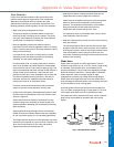
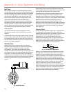
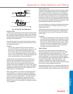
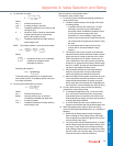
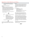
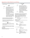
Three-way Valves
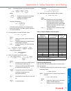
Three-way valves (Fig. 12) control the flow of liquids in mixing or
diverting valve applications (Fig. 13). The internal design of a
three-way globe valve enables it to seat against the flow of
liquid in the different applications. An arrow cast on the valve
body indicates the proper direction of liquid flow. It is important
to connect three-way valve piping correctly or oscillations,
noise, and excessive valve wear can result. Three-way valves
are typically have linear flow characteristics, although, some are
equal percentage for flow through the coil with linear flow
characteristics for flow through the coil bypass. Ball valves are
also available in a three-way configuration, while two butterfly
valves can be made to act as a three-way valve.
Fig. 12. Three-Way Valves.
Stem Flow
Change Position Rate Change
— 30% open 3.9 gpm —
10% increase 40% open 6.2 gpm 60% increase
10% increase 50% open 9.9 gpm 60% increase
HEAT OUTPUT
HEAT OUTPUT
C2333
100%
0% 100%
FLOW
90%
10%
100%
0% 100%
STEM TRAVEL
FLOW
90%
100%
0% 100%
STEM TRAVEL
90%
10%
GRAPH A GRAPH B GRAPH C
50%
50%
50%
10%
50%
50%
50%
90%
10%
OUT
I
N
MIXING
VALVE
C2334A
DIVERTING
VALVE
IN
OUT
IN
O
U
T
Appendix A: Valve Selection and Sizing