


126
Unitary Valve
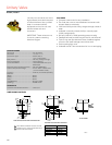
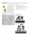
VU52; VU53
VU52; VU53
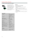
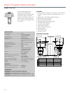
Two-way Fan Coil Valves, the VU53
high pressure zone valves are used
to control the flow of hot or chilled
water in commercial HVAC
equipment such as fan coil units,
terminal reheat coils and
convectors.
IMPORTANT: These valves are not
for use in systems containing
dissolved oxygen.
SPECIFICATIONS
Valve Type ............................................Fan Coil Valve
Valve Size ............................................1/2; 3/4; or 1 in.
Connection Type ..................................Sweat; NPT; or
1/2 in. Inverted flare
Body Pattern ........................................Two-way, Straight-through
Flow Characteristic ..............................Quick Opening
Controlled Medium ............................... Hot/Chilled Water with up to
60% Glycol
Maximum Safe Operating Pressure ..... 300 psig (2068 kPa)
Ambient Temperature Range ............... 34 F to 125 F at 200 F Fluid
(1 to 52 C @ 94 C Fluid)
Actuation ..............................................Must be purchased separately
Materials
(Body) ..................................................Brass
(Stem) ................................................... Brass
(Seat) .................................................... Brass
(Plug/Ball/Disc) ....................................Buna-N rubber
(Packing) .............................................. EPDM rubber
APPROVALS
Canadian Standards Association ........CSA C/US
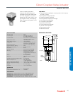
FEATURES
• Compact construction for easy installation.
• Fits under the cover of most baseboard convectors with
actuator fitted to valve body.
• VU52 and VU53 provide 2-way, straight-through control of
water.
• Available in normally closed (VU53) or normally open
(VU52) configurations.
• 300 psi (2,000 kPa, PN20) operating pressure rating.
• Patented ball seal provides long service life, soft close off.
• Triple O-ring seal provides three lines of defense against
corrosion and water leakage around drive shaft.
• Quick opening flow curve.
• Available with NPT end connections for iron or steel piping.
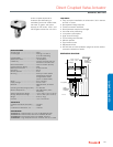
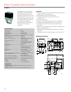
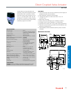
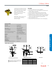
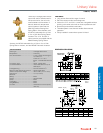
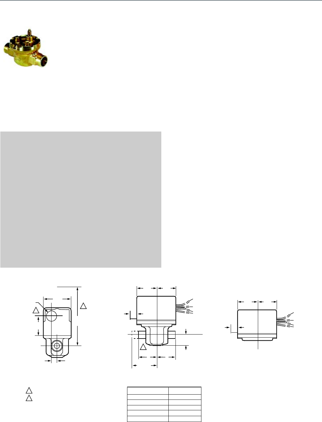
DIMENSIONS DIAGRAM
2
2
1
1
VU52 AND VU53 VALVE WITH VU448 ACTUATOR
VU52 AND VU53 VALVE WITH ACTUATOR
VU ACTUATOR
2-3/8
(60)
7/8 DIA.
(22)
1-1/2
(38)
3-3/4
(133)
15/32
(12)
3/8
(10)
1-3/4
(44)
1-3/4
(44)
A
A
B
7
3/8
(10)
A
2-1/8 (54)
(INVERTED
FLARE)
1-3/4
(44)
1-3/4
(44)
7/8 (22)
2-WAY
VALVE BODY SIZE A
1/2 IN. SWEAT 1-5/6 (33)
3/4 IN. SWEAT 1-3/8 (35)
1 IN. SWEAT 1-11/16 (43)
1/2 IN. NPT 1-3/8 (35)
3/4 IN. NPT 1-11/16 (43)
HEIGHT NEEDED TO REMOVE ACTUATOR OR COVER
OPENING FOR 1/2 IN. CONDUIT ON OPPOSITE SITE OF
MANUAL LEVER FOR ALL MODELS.
M16818