


253
APPENDIX
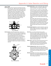
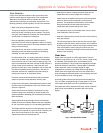
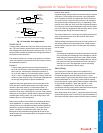
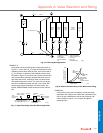
Fig. 13. Three-Way Valve Applications.
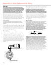
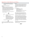
MIXING VALVE
A mixing valve provides two inlet ports and one common outlet
port. The valve receives liquids to be mixed from the inlet ports
and discharges the liquid through the outlet port (Fig. 12). The
position of the valve disc determines the mixing proportions of
the liquids from the inlet ports.
The close-off pressure in a mixing valve equals the maximum
value of the greater inlet pressure minus the minimum value of
the downstream pressure.
EXAMPLE:
A mixing valve application has a maximum pressure of
25 psi on one inlet port, maximum pressure of 20 psi on the
other inlet port, and minimum downstream pressure of
10 psi on the outlet port. The close-off pressure is 25 psi –
10 psi = 15 psi. The application requires a mixing valve with
at least a 15 psi close-off rating. The actuator selected must
have a high enough force to operate satisfactorily.
In globe mixing valve applications, the force exerted on the
valve disc due to unbalanced pressure at the inlets usually
remains in the same direction. In cases where there is a
reversal of force, the force changes direction and holds the
valve disc off the seat, cushioning it as it closes. If the pressure
difference for the system is greater than the pressure ratings of
available globe mixing valves, use a ball mixing valve or two
butterfly valves in a tee configuration.
Globe mixing valves are not suitable for modulating diverting
valve applications. If a mixing valve is piped for modulating
diverting service, the inlet pressure slams the disc against the
seat when it nears the closed position. This results in loss of
control, oscillations, and excessive valve wear and noise.
Mixing valves are acceptable using about 80 percent of the
close-off rating, but not recommended, in two-position diverting
valve applications.
DIVERTING VALVE
A globe diverting valve provides one common inlet port and two
outlet ports. The diverting valve uses two V-port plugs which
seat in opposite directions and against the common inlet flow.
The valve receives a liquid from one inlet port and discharges
the liquids through the outlet ports (Fig. 12) depending on the
position of the valve disc. If the valve disc is against the bottom
seat (stem up), all the liquid discharges through the side outlet
port. If the valve disc is against the top seat (stem down), all the
liquid discharges through the bottom outlet port.
The close-off pressure in a diverting valve equals the maximum
value of the inlet pressure minus the minimum value of the
downstream pressure.
Globe diverting valves must not be used for mixing service. As
with mixing valves used for diverting service, media pressure
drop across the valve can cause it to slam shut with resulting
loss of control.
EXAMPLE:
A diverting valve application has 20 psi maximum on the inlet
port, one outlet port discharging to the atmosphere, and the
other outlet port connecting to a tank under 10 psi constant
pressure. The pressure difference between the inlet and the
first outlet port is 20 psi and between the inlet and second
outlet port is 10 psi. The application requires a diverting
valve with at least 20 psi close-off rating.
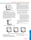
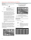
Valve Sizing
Every valve has a capacity index or flow coefficient (C
v
).
Typically determined for the globe and ball valves at full open
and about 60 degrees open for butterfly valves. C
v
is the
quantity of water in gpm at 60F that flows through a valve with a
pressure differential of 1 psi. Sizing a valve requires knowing
the medium (liquid or gas) and the required pressure differential
to calculate the required C
v
. When the required C
v
is not
available in a standard valve, select the next closest and
calculate the resulting valve pressure differential at the required
flow to verify to verify acceptable performance.
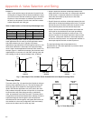
After determination of the valve C
v
, calculation of the flow of any
medium through that valve can be found if the characteristics of
the medium and the pressure drop across the valve are known.
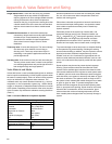
C2335A
LOAD
LOAD
SUPPLY
THREE-WAY
DIVERTING VALVE
RETURN
B. LOAD BYPASS IN DIVERTING VALVE APPLICATION
BYPASS
HOT
WATER
SUPPLY
THREE-WAY
MIXING VALVE
BYPASS
HOT
WATER
RETURN
A. LOAD BYPASS IN MIXING VALVE APPLICATION
Appendix A: Valve Selection and Sizing