


33
Microphone Input module should be started
with contact 1-8 of the Control Input
Module. See user programming 14.3 menu
item 3.8 ‘Control inputs 1-8’.
Relays 3-12
Relays 3 (or 4 if power-on delay is used) to
12 can be activated by different sources, and
may be used for a number of functions.
Remote Volume Control Overrides
The ‘make’ contacts of Relays 3 to 12 may
be used to activate up to 10 loudspeaker
volume control override relays. These relays,
mounted in the loudspeaker enclosures,
override the volume control setting of the
actual loudspeaker itself. This means that
regardless of the individual ‘music’ volume
setting of each loudspeaker, all the
loudspeakers in a particular zone will work
at full volume when a Call is routed to it.
13.2 Installation
Mounting in the Control Centre
One Control Relay Module is used in
SM30. This must be located in Control
Centre slot J, as indicated in fig.5.1.
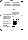
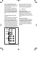
Wiring Control Relays
Each Control Relay Module is supplied with
two plug-in, 16 terminal, screw connector
blocks (fig.13). The wires to remote
equipment are connected to the screw
terminals, which are marked in threes 1 to 8
(make and break contacts), and in pairs 9 to
12 (make contact). The great advantage of
the connector block is that if, for some
reason, the SM30 Control Centre has to be
removed, the blocks have simply to be
unplugged and the wires remain intact. This
avoids the tedious and risky business of
rewiring the blocks in their original
configurations.
13.3 Programming
Power-on delay
The Power-on delay function can be
programmed with a time delay of 2-9
seconds (see installer programming 14.7
menu 5 ‘Power-on delay’).
Coupling relays to zones
Each Control Relay is programmable,
‘linked’ or ‘locked’, to a specific Zone Relay,
so that when a call is routed to a loudspeak-
er zone, the Control Relay linked to it will
activate automatically (see installer program-
ming 14.7 menu 11 ‘Override relays’). The
display will show ‘Z’ for the relays involved.
Activation by Call Station and Function
Keys
Relays 3 (or 4, if power on delay is used) to
12 may be programmed to be activated by
Call Stations, and Function Keys on Call
Stations. Activation by a Call Station
happens whenever a call is made using
Keypad of the Call Station Keypad (see user
programming 14.3 menu 1.7). Activation by
a Function Key happens whenever a pre-
programmed Function Key (followed by the
‘Press-To-Talk’ key) is pressed (see user
programming 14.3 menu 1.14).
Activation by Control Inputs
Relays 3 (or 4, if power on delay is used) to
12 may also be programmed to be activated
by Control Input contacts (see user
programming 14.3 menu 3.12). Control
Input contacts 5 to 8 can be programmed to
activate one, or a group of, Control Relay(s).
This means that when the remote switch of
a control input is closed, the programmed
Control Relays become activated (see user
programming 14.3 menu 3.7).
The display will show ‘A’ for the relays
involved.
GB/SM 30 user manual 5/26/98 10:18 AM Page 33