


30
12 ZONE RELAY MODULE
(ZRM) LBB 1287
The SM30 system is intended for use with 2
separate amplifiers, or two separate channels
of a multi channel amplifier. One channel
will handle the ‘Call’ signal, and the other
channel will amplify the ‘Music’ signal.
This allows the music signal to continue,
uninterrupted, when a call is made to other
loudspeaker zones.
Both the Call and Music signals are
processed via SM30, and are available on the
output on the Line Output Module. The
signals are then amplified by their separate
power amplifiers, and the amplified signals
return to SM30, via the inputs of the Zone
Relay Module.
The SM30 software uses the relays of the
Zone Relay Modules to route the separate
signals to their relevant loudspeaker zones.
Each Zone Relay Module is capable of
routing the amplified Call and Music signals
to 6 separate loudspeaker zones. Up to 3
units may be installed in the Control
Centre, giving SM30 the capacity to route
the signals to 18 loudspeaker zones.
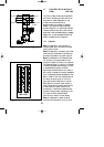
12.1 Installation
Mounting in the Control Centre
Up to three Zone Relay Modules can be
installed in the Control Centre, in slots G,
H, & I, as illustrated in fig.5.1.
The numbers designated to Loudspeaker
Zones by the microprocessor are dependent
on the slot in which the Zone Relay Module
is located. If, for instance, only one Zone
Relay Module is used in a system, and that
module is located in slot I, then the six
loudspeaker zones would be numbered 1-6.
If the same module were plugged into slot
H, instead of I, then the loudspeaker zones
would be numbered 7-12, regardless of the
fact that they are the only loudspeaker zone
outputs in the system. This should be taken
into consideration when planning the
location of the Zone Relay Module(s) in the
Control Centre.
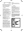
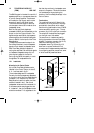
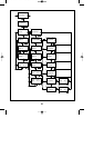
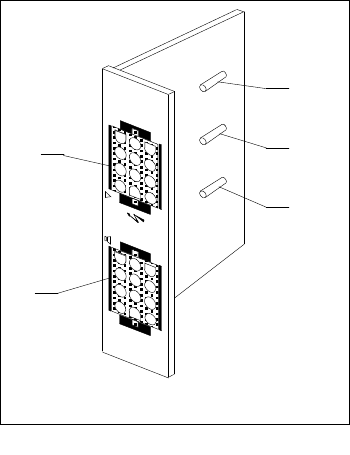
Terminations
The module is fitted with 2 ‘Mate-N-Lok
connectors. All wiring is done in the plugs
provided with the module, which means
that the wiring itself remains intact if SM30
is ever removed for servicing, etc.. The top
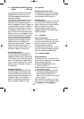
connector (fig.12.1B) is the input connector.
The outputs of the amplifiers are plugged
into the right row of the sockets.
The centre row of 4 sockets are used for
linking the module to the next Zone Relay
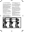
Module. The bottom connector (fig.12.1A)
feeds the routed outputs to the 6
loudspeaker zones. Fig.12.2 and fig.12.3
show how to connect the Mate-N-Lok
connectors and illustrates several possibilities
for configuring amplifier connections, some
of which are briefly described below.
Fig. 12.1 - ZRM
B
A
F3
F2
F1
LBB 1287
GB/SM 30 user manual 5/26/98 10:18 AM Page 30