


20
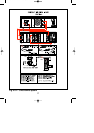
6.2 Installation
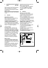
Loudspeaker Zone Template
A paper template is provided, on which the
names of the loudspeaker zones can be
written. The template has a detachable blank
section at the bottom, allowing it to be used
in a typewriter.
To mount the template in the Call Station,
first remove the right hand side cheek
(fig.6.1D), by unscrewing the two screws in
its side (fig.6.1E), and the one screw located
in the bottom. The plastic template cover
(fig.6.1C) can now be slid out. Place the
(type) written template in position over the
zone LEDs (having first torn off its blank
perforated panel), and carefully slide the
plastic template cover back in place.
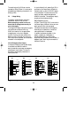
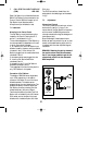
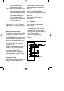
Connection to Control Centre
Between the Call Station and the Call
Station Input Module (see chapter 7.1) the
following cabling is needed::
■ a shielded twisted pair for audio and
power transport;
■ a twisted pair for data transport.
When the copper diameter of each wire is
not less than 0.75 mm2 the length of the
cable can be up to 1000 meters for proper
functioning.
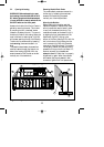
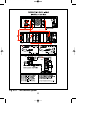
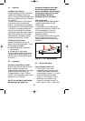
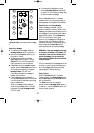
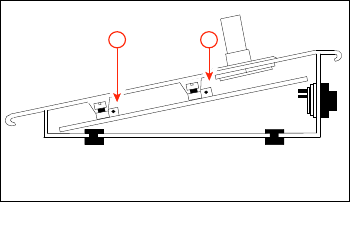
6.3 Adjustments
Microphone Pre-amplifier Gain Preset
With the right hand side cheek of the Call
Station removed, the microphone
preamplifier’s gain can be preset. Turning the
potentiometer (fig.6.2B) to the right
increases the amount of gain. To obtain
nominal 1 Volt output level, the gain can be
preset from 84 to 114 dB SPL.
NOTE: The Call Station Input Modules
also have input gain presets. The
Microphone Preamplifier Gain Preset
should only be used for setting the
amount of compression, not for lining up
the Call Station output with the rest of
the SM30 System. See ‘Built-in
Compressor’ earlier in this chapter.
LED Intensity Preset
With the right hand side cheek removed, it
is possible to gain access to the LED
intensity preset.
To compensate for various local lighting
conditions, the illumination intensity of the
LEDs can be adjusted. Turning the
potentiometer (fig.6.2A) to the right
increases the intensity.
With the template and its cover in position,
and the microphone volume and LED
intensity adjusted, replace the right hand
side cheek.
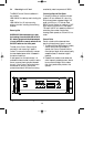
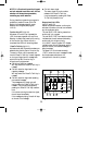
6.4 Using the Call Station
Using the Keypad to make a Call
1 To route a call to one or more
loudspeaker zones, simply type in the
number of each desired zone using the
numeric keypad. Numbers ‘1’ to ‘9’ allow
single digit numbers to be entered,
number ‘1-’ is for tens, and ‘0’ is the
second digit in the number 10. For
instance, to route a call to zones 7, 10,
and 15, type in: 7, then 1-, then 0; then
Fig. 6.2 - CST adjustments
A
B
GB/SM 30 user manual 5/26/98 10:18 AM Page 20