


11
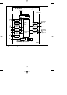
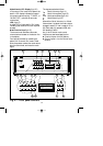
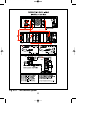
5. SETTING UP THE HARDWARE
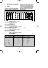
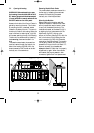
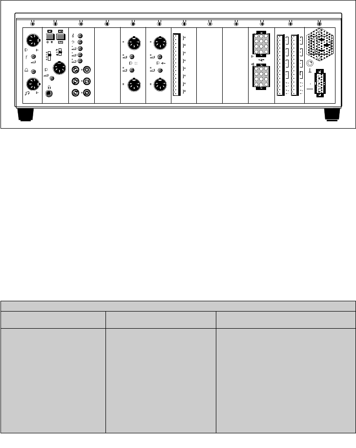
5.1 General
The SM30 Control Centre is delivered with
only the Line Output Module (LOM) and
the Power Supply Module (PSM) mounted
in their slots. All other modules must be
fitted into their respective slots as indicated
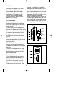
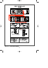
in fig.5.1. A survey of configurations with
the maximal number of input modules is
given in the table.
LOM RMM MUM
MIM
ZRM CRM PSM
A
B
C
D
E
G
F
H
I
J
CIMCSM
LBB 1285 LBB 1286
LBB 1284
LBB 1287 LBB 1288
9
1
3
5
7
10
8
6
4
2
1112
LBB 1283
LBB 1282
Line Output Module X
Music and call output signal to amplifier
LBB 1285/00 Recorded Message Module A
4 messages = 29,5 sec
LBB 1286/10 Music Input Module B
3 music sources
LBB 1282/00 Microphone Input Module CDE
2 microphones max. 3 modules = 6 microphones
LBB 1283/00 Call Station Input Module CDE
2 Call Stations max. 3 modules = 6 Call Stations
LBB 1284/00 Contact Input Module DE F
8 contacts max. 3 modules = 24 contacts
LBB 1287/00 Zone Relay Module GHI
6 loudspeaker zones max. 3 modules = 18 zones
LBB 1288/00 Control Relay Module J
12 relays, only 9 or 10 relays free to programme
Power Supply Module X
220 V mains supply +48 V battery supply
Fig. 5.1
Maximal configuration of input modules
CSM pos Call Station numb. MIM pos Microphone numb. CIM pos Contact numb.
- - - - F,E,D, 1/8, 9/16, 17/24
- - C 5/6 F,E,D, 1/8, 9/16, 17/24
- - D,C 3/4, 5/6 F,E 1/8, 9/16
- - E,D,C 1/2, 3/4, 5/6 F 1/8
C 5/6 - - F,E,D 1/8, 9/16, 17/24
C 5/6 D 3/4 F,E 1/8, 9/16
C 5/6 E,D 1/2, 3/4 F 1/8
D,C 3/4, 5/6 - - F,E 1/8, 9/16
D,C 3/4, 5/6 E 1/2 F 1/8
E,D,C, 1/2, 3/4, 5/6 - - F 1/8
GB/SM 30 user manual 5/26/98 10:18 AM Page 11