


24
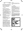
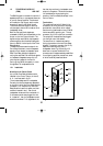
Connection of Microphones
The design of SM30 allows a single cable to
be used to connect a Microphone to one of
the sockets of the Microphone Input
Module.
This cable has two screened wires, plus two
unscreened wires.
The screened wires carry the audio signal
and phantom powering, and the unscreened
wires are connected to the remote switch of
the microphone. Terminate the cable at side
of the microphone with a lockable 5-pole
180° DIN female socket, and at the side of
the Input Module with a lockable 5-pole
180° DIN male socket.
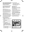
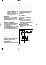
The DIN connections, viewed from the
solder side of the cable plugs, are illustrated
in fig.8.
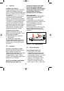
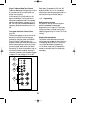
8.3 Adjustments
Gain Control Potentiometers
The 2 front panel controls are input gain
controls, used for “lining up” the volume
level of the microphone with the rest of the
SM30 signal sources (Call Stations, attention
signals, pre-recorded messages, background
music players, etc.). Because the strength of
each person’s voice differs, set each gain
control “by ear” so that a clear, comfortable
listening level is attained, which is in balance
with the other amplified signals.
9 CONTROL INPUT MODULE
(CIM) LBB 1284
Each Control Input Module allows eight
remote switches to be connected to the
Control Centre. Up to 3 Control Input
Modules can be located in the SM30
Control Centre allowing a total of 24
remote switches to be used, but resulting in
less of Call Station Input Modules and
Microphone Input Modules. When a remote
switch closes the normally open circuit, the
Control Input circuit senses this, and the
SM30 microprocessor carries out a series of
actions.
9.1 Operation
All Control Inputs
Each Control Input can be programmed to
carry out SM30 switching functions,
including:
■ Activation of one of the SM30 attention
or alarm signals.
■ Activation of a pre-recorded message.
■ Routing of the above listed signals to
loudspeaker zones, after giving the call a
programmed priority status.
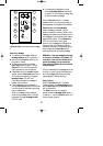
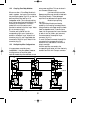
Inputs 1 to 8 of first CIM (fig.5.1F).
Apart from the above listed functions, inputs
1-4 may be given an alternative function.
This allows remote control of the Music
Function Keys, located on the front panel of
the SM30 Control Centre:
Input 1 Music volume up activation
Input 2 Music volume down activation
Input 3 Music mute on/off
Input 4 Music source selection
Input 5-8 Apart from the normal switching
functions, inputs 5-8 may be
programmed to activate Control
Relays, which can be used to start
GB/SM 30 user manual 5/26/98 10:18 AM Page 24