


28
The Function switch must be in its lowest
(system) position for messages to be replayed
through the system.
When the Function switch is in its top
(record) or middle (monitor) position,
SM30 will not be able to use the Recorded
Message function, and the messages already
recorded will not be accessible to the user.
An ERROR warning will be seen on the
display of the Control Centre, indicating
that the Message Module is not in its
‘system’ mode.
If the Function switch is in the top (record)
position, and the Message Selection switch
is moved to a position where a message is
already recorded, the green Message Present
LED illuminates to warn that a message is
present at that position.
Remote Location Recording
Because the Record and Monitor functions
are independent of the SM30
microprocessor, the unit may be taken out of
the Control Centre, and transported to a
remote location.
There, with the aid of suitable power
supplies of +5 V and +35 V, the module
may be used to record the messages in a
more suitable/convenient recording
environment. Refer to the service
documentation of SM30 how to make the
connections.
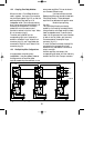
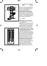
11 MUSIC INPUT MODULE
(MUM) LBB 1286/10
The ability of SM30 to play music, which is
uninterrupted, even though the system is
handling a call routed to other loudspeaker
zones, is an important feature of the system.
To make best use of this feature, Philips have
developed the Music Input Module. The
module enables 3 independent music sources
to be connected to the Control Centre.
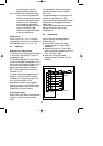
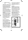
11.1 Installation
Mounting in the Control Centre
One Music Input Module may be installed
in the Control Centre.
This module must be located in slot B as
illustrated in fig.5.1.
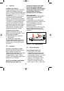
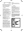
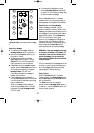
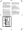
Music Source Inputs
The module provides 3 sets of double cinch
sockets (fig.11A) for connection of the
music sources. The double sockets allow
stereo signal sources to be connected, using
standard double cinch/ cinch Hi-Fi cables.
The stereo signal is mixed to mono in the
module. A mono signal (e.g. from a radio
tuner) should simply be plugged into either
one of the two sockets.
11.2 Adjustments
Individual Input Volume Controls
Three potentiometers (fig.11B)
corresponding to the three inputs, give the
user/installer the capability of setting the
input volume levels of each source
independently.
Adjust the source signal levels so that when
the operator selects a different source, no
great change in music volume level occurs.
GB/SM 30 user manual 5/26/98 10:18 AM Page 28