


22
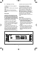
7 CALL STATION INPUT MODULE
(CSM) LBB 1283
Each Call Station Input Module allows two
SM30 Call Stations to be connected to the
Control Centre. SM30 will accept up to 3
Call Station Input Modules and/or
Microphone Input Modules in total.
7.1 Installation
Mounting in the Control Centre
The Call Station Input Modules must be
located in the Control Centre slots E, D,
and/or C, as indicated in fig. 5.1.
The number designated to a Call Station by
the microprocessor is dependent on the slot
in which the module is located.
If, for instance, only one Call Station Input
Module is used in a system, and that module
is located in slot E, then the two Call
Stations plugged into the module would be
numbered 1 and 2.
If the same module were plugged into slot
D, then the Call Stations would be
numbered 3 and 4.
If plugged into slot C, the Call Stations
would be numbered 5 and 6.
This regardless of the fact that they are the
only Call Stations in the system.
Connection of Call Stations
The design of SM30 allows a single cable,
up to 1000 metres long, to be used to
connect a Call Station to one of the Input
Module’s sockets. This cable has two
screened wires, plus two twisted wires. The
screened wires carry the audio signal and
Call Station phantom powering, and the
twisted wires carry the control signal.
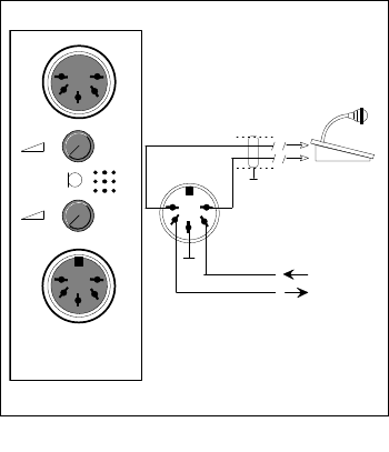
Terminate the cable at the side of the Call
Station with a lockable 5-pole 180° female
DIN socket, and at the side of the Input
Module with a lockable 5-pole 180° male
DIN plug.
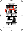
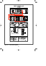
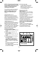
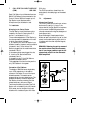
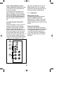
The DIN connections, viewed from the
solder side of the cable plugs, are illustrated
in fig.7.
7.2 Adjustments
Volume Level Controls
The 2 front panel controls are input volume
level controls, used for “lining up” the
volume level of the Call Station microphone
with the rest of the SM30 signal sources
(microphones, attention signals, background
music players, etc.).
Since the strength of each person’s voice
differs, set each volume level “by ear” so that
a clear, comfortable listening level, which is
in balance with the other amplified signals,
is attained.
REMARK: Reducing the gain by means of
the module volume level controls means
that it is no longer possible to get the full
volume level output from the connected
SQ45 amplifiers.
Fig. 7 - CSM
1
2
2
1
2
LED Data
Key Data
LBB 1283
1
4
2
3
5
}
GB/SM 30 user manual 5/26/98 10:18 AM Page 22