


25
remote equipment, activate
signalling/warning lamps, etc..
Input 1-8 Apart from the normal functions,
inputs 1-8 can be programmed to
distribute an external audio source
connected to a Microphone Input
Module to zone 1-36 preceded
with an attention signal and/or
pre-recorded message. in that case
relay 4 of the Control Relay
Module of the basic frame is used
to start the audio source.
Direct routing
Control inputs 1-6, 1-12, or 1-18 can be
programmed to route a call or music directly
to loudspeaker zones 1-6, 1-12, or 1-18.
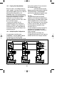
9.2 Installation
Mounting in the Control Centre
The Control Input Modules must be located
in the Control Centre slots F, E, and/or D,
as indicated in fig.5.1.
The numbers designated to Control Inputs
by the microprocessor are dependent on the
slot in which their module is located. If only
one Control Input Module is used in the
system, that module should be located in
slot F, then the eight Control Inputs are
numbered 1 to 8.
If another module were plugged into slot E
instead of F, then the Control Inputs are
numbered 9 to 16. Accordingly, slot D will
carry inputs numbered 17 to 24.
Note should be taken of the paragraphs
referring to Inputs 1-4 and Inputs 5-8 when
planning the location of the Control Input
Module(s) in the Control Centre.
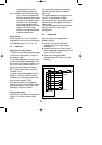
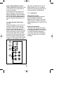
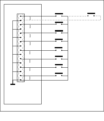
Wiring control inputs
Each Control Input Module is supplied with
a plug-in, 16 terminal, screw connector
block.
The remote switch wires are connected to
the screw terminals, which are marked in
pairs 1 to 8.
The great advantage of the connector block
is that if, for some reason, the SM30
Control Centre has to be removed, the block
has simply to be unplugged and the wires
remain intact.
This avoids the tedious and risky business of
rewiring the blocks in their original
configurations.
9.3 Programming
Control inputs can be programmed for
different facilities:
■ normal Call activation (see installer
programming par.14.7 menu 8 ‘Store
Hardware’);
■ remote music control or Control Relay
switching (see user programming par.14.3
menu 3 ‘Control Inputs’);
■ direct zone routing (see installer
programming par.14.7 menu 13 ‘Direct
Routing’).
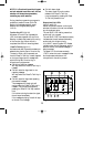
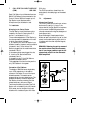
Fig. 9 - CIM
1
2
3
4
5
6
7
8
Common return
LBB 1284
Individual
return
GB/SM 30 user manual 5/26/98 10:18 AM Page 25