


73
5-5 Ladder Diagram Instructions
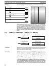
Ladder diagram instructions include ladder instructions and logic block in-
structions. Ladder instructions correspond to the conditions on the ladder
diagram. Logic block instructions are used to relate more complex parts of
the diagram that cannot be programmed with ladder instructions alone.
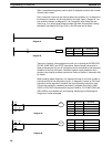
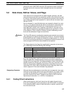
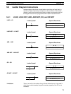
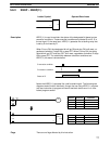
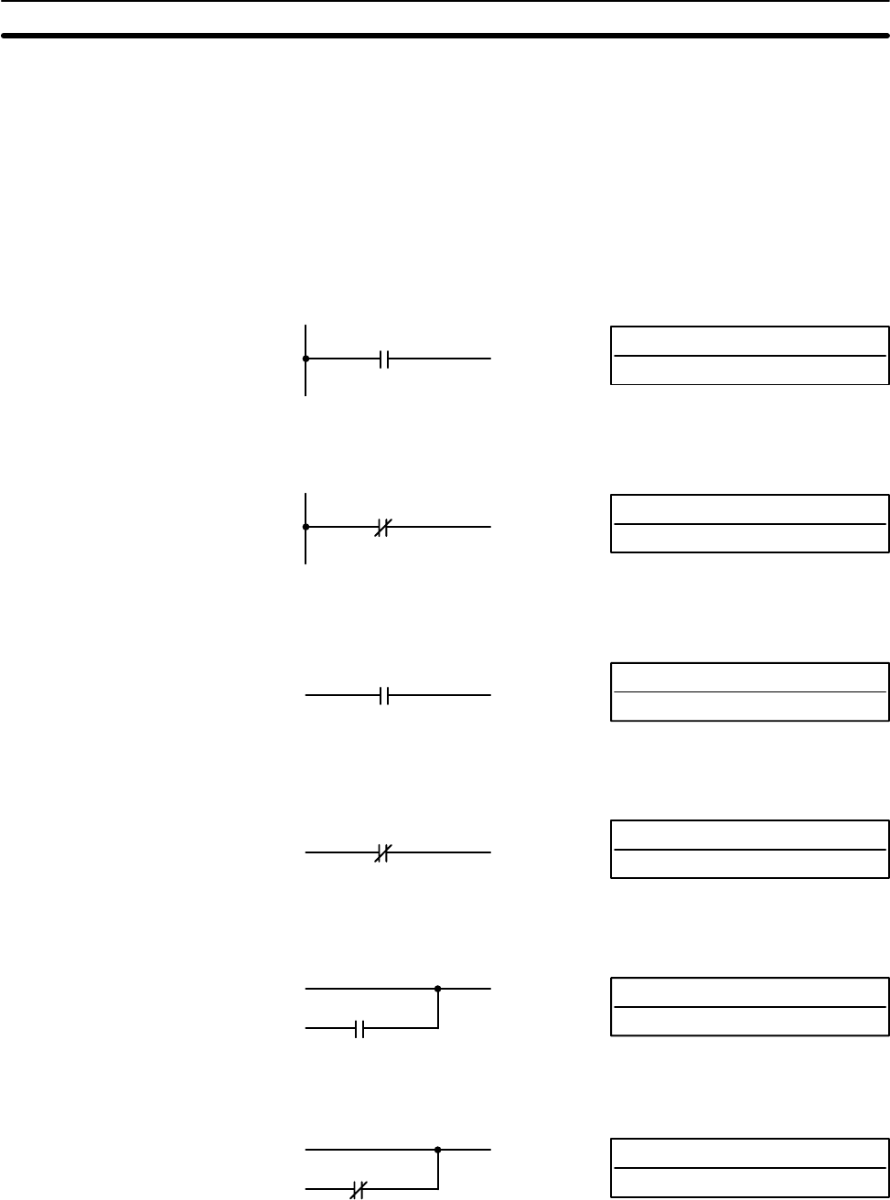
5-5-1 LOAD, LOAD NOT, AND, AND NOT, OR, and OR NOT
B: Bit
IR, SR, HR, TC, TR
Ladder Symbol Operand Data Areas
LOAD – LD
B
B: Bit
IR, SR, HR, TC, TR
Ladder Symbol Operand Data Areas
LOAD NOT – LD NOT
B
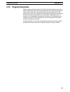
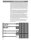
B: Bit
IR, SR, HR, TC, TR
Ladder Symbol Operand Data Areas
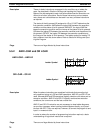
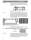
AND – AND
B
B: Bit
IR, SR, HR, TC, TR
Ladder Symbol Operand Data Areas
AND NOT – AND NOT
B
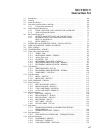
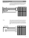
B: Bit
IR, SR, HR, TC, TR
Ladder Symbol Operand Data Areas
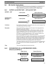
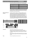
OR – OR
B
B: Bit
IR, SR, HR, TC, TR
Ladder Symbol Operand Data Areas
OR NOT – OR NOT
B
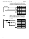
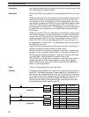
There is no limit in the number of any of these instructions or in the order in
which they must be used as long as the memory capacity of the PC is not
exceeded.
Limitations
Ladder Diagram Instructions Section 5-5