


23
SR bit 1904 turns ON when there is a carry in the result of an arithmetic op-
eration. The content of CY is also used in some arithmetic operations, e.g., it
is added or subtracted along with other operands. This flag can be set and
cleared from the program using the SET CARRY and CLEAR CARRY in-
structions. Use CLC before any instruction using CY unless the current con-
tent of CY is required.
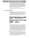
SR bit 1905 turns ON when the result of a comparison shows the second of
two 4-digit operands to be greater than the first.
SR bit 1906 turns ON when the result of a comparison shows two operands
to be equal or when the result of an arithmetic operation is zero.
SR bit 1907 turns ON when the result of a comparison shows the second of
two 4-digit operands to be less than the first.
Remember that the previous four flags, CY, GR, EQ, and LE, are cleared by
the END instruction.
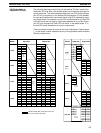
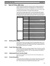
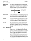
3-5 Data Memory (DM) Area
The DM area is used for internal data storage and manipulation and is acces-
sible only by word. Addresses range from DM 00 through DM 63.
Although composed of 16 bits just like any other word in memory, DM words
cannot be specified by bit for use in instructions with bit-size operands, such
as LD, OUT, AND, and OR.
When the RDM (REVERSIBLE DRUM COUNTER) is used the DM area
words 00 to 31 are used as the area where the upper and lower limits of the
counter are preset and as such these words cannot be used for any other
purposes.
When the HDM (HIGH-SPEED DRUM COUNTER) is used the DM area
words 32 to 63 are used as the area where the upper and lower limits of the
counter are preset and as such these words cannot be used for any other
purposes.
The DM area retains status during power interruptions.
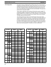
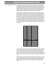
3-6 Holding Relay (HR) Area
The HR area is used to store and manipulate various kinds of data and can
be accessed either by word or by bit. Word addresses range from HR 0
through HR 9; bit addresses, from HR 000 through HR 915. HR bits can be
used in any order required and can be programmed as often as required.
The HR area retains status when the system operating mode is changed, or
when power is interrupted.
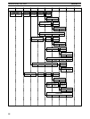
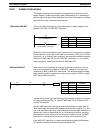
3-7 Timer/Counter (TC) Area
The TC area is used to create and program timers and counters and holds
the completion flags, set values (SV), and present values (PV) for all timers
and counters. All of these are accessed through TC numbers ranging from
TC 00 through TC 47. Each TC number is defined as either a timer or
counter using one of the following instructions: TIM, TIMH, CNT or CNTR. No
prefix is required when using a TC number in a timer or counter instruction.
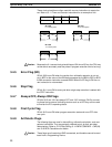
Carry Flag, CY
Greater Than Flag, GR
Equal Flag, EQ
Less Than Flag, LE
Note
Timer/Counter (TC) Area Section 3-7