


64
Often, complicated programs are the result of attempts to reduce the number
of times a bit is used.
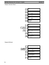
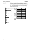
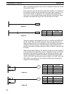
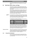
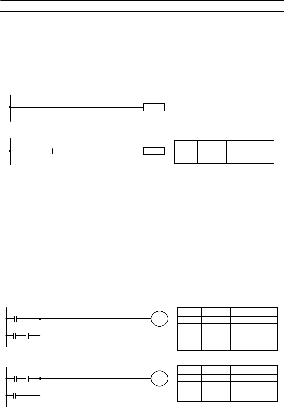
Every instruction line must also have at least one condition on it to determine
the execution condition for the instruction at the right. Again, diagram A , be-
low, must be redrawn as diagram B. If an instruction must always be exe-
cuted (e.g., if an output must always be kept ON while the program is being
executed), the Always ON Flag (1813) in the SR area can be used.
Instruction
1813
Instruction
Diagram A
Diagram B
Address Instruction Operands
0000 LD 1813
0001 Instruction
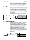
There are, however, a few exceptions to this rule, including the INTERLOCK
CLEAR, JUMP END, and STEP Instructions. Each of these instructions is
used as the second of a pair of instructions and is controlled by the execution
condition of the first of the pair. Conditions should not be placed on the in-
struction lines leading to these instructions. Refer to
Section 5 Instruction Set
for details.
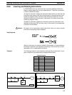
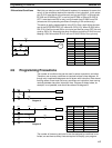
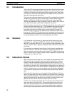
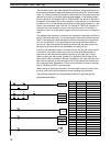
When drawing ladder diagrams, it is important to keep in mind the number of
instructions that will be required to input it. In diagram A, below, an OR Load
instruction will be required to combine the top and bottom instruction lines.
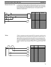
This can be avoided by redrawing as shown in diagram B so that no AND
LOAD or OR LOAD instructions are required. Refer to
5-5-2
AND LOAD and
OR LOAD
for more details and
4-6 Inputting, Modifying and Checking the
Program
for further examples.
0000
0001 0207
0207
0001
0000
0207
0207
Diagram A:
Diagram B:
Address Instruction Operands
0000 LD 0000
0001 LD 0001
0002 AND 0207
0003 OR LD ---
0004 OUT 0207
Address Instruction Operands
0000 LD 0001
0001 AND 0207
0002 OR 0000
0003 OUT 0207
Programming Precautions Section 4-9