


91
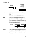
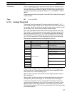
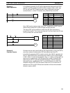
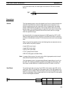
In the following example, the PV will be decremented whenever both 0000
and 0001 are ON provided that 0002 is OFF and either 0000 or 0001 was
OFF the last time CNT 04 was executed. When 150 pulses have been
counted down (i.e., when PV reaches zero), 0205 will be turned ON.
0000
CP
R
CNT 04
#0150
0002
0001
0205
CNT 04
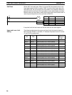
Address Instruction Operands
0000 LD 0000
0001 AND 0001
0002 LD 0002
0003 CNT 04
# 0150
0004 LD CNT 04
0005 OUT 0205
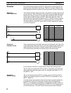
Here, 0000 can be used to control when CNT is operative and 0001 can be
used as the bit whose OFF to ON changes are being counted.
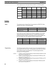
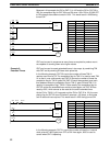
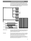
The above CNT can be modified to restart from SV each time power is
turned ON to the PC. This is done by using the First Cycle flag in the SR area
(1815) to reset CNT as shown below.
0000
CP
R
CNT 04
#0150
0002
0001
0205
CNT 04
1815
Address Instruction Operands
0000 LD 0000
0001 AND 0001
0002 LD 0002
0003 OR 1815
0004 CNT 04
# 0150
0005 LD CNT 04
0006 OUT 0205
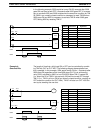
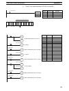
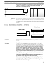
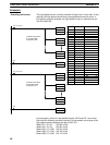
Counters that can count past 9,999 can be programmed by using one CNT to
count the number of times another CNT has reached zero from SV.
In the following example, 0000 is used to control when CNT 01 operates and
CNT 01, when 0000 is ON, counts down the number of OFF to ON changes
in 0001. CNT 01 is reset by its completion flag, i.e., it starts counting again as
soon as its PV reaches zero. CNT 02 counts the number of times the com-
pletion flag for CNT 01 goes ON. Bit 0002 serves as a reset for the entire
extended counter, resetting both CNT 01 and CNT 02 when it is OFF. The
completion flag for CNT 02 is also used to reset CNT 01 to inhibit CNT 01
operation once PV for CNT 02 has been reached until the entire extended
counter is reset via 0002.
Example 1:
Basic Application
Example 2:
Extended Counter
Timer and Counter Instructions Section 5-11