


27
Most instructions have at least one or more operands associated with them.
Operands indicate or provide the data on which an instruction is to be per-
formed. These are sometimes input as the actual numeric values, but are
usually the addresses of data area words or bits that contain the data to be
used. For instance, a MOVE instruction that has IR 00 designated as the
source operand will move the contents of IR 00 to some other location. The
other location is also designated as an operand. A bit whose address is des-
ignated as an operand is called an operand bit; a word whose address is
designated as an operand is called an operand word.
Other terms used in describing instructions are introduced in
Section 5 In-
struction Set
.
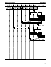
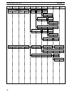
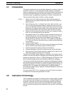
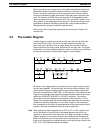
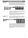
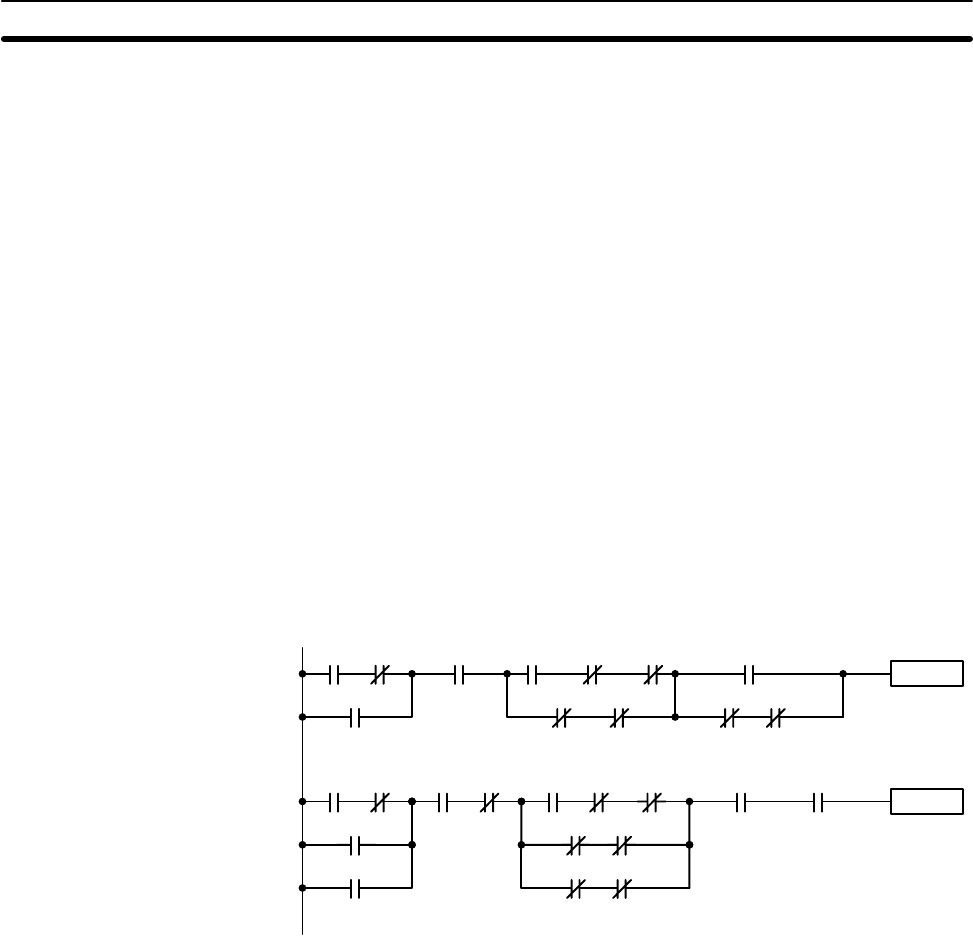
4-3 The Ladder Diagram
A ladder diagram consists of one line running down the left side with lines
branching off to the right. The line on the left is called the bus bar; the
branching lines, instruction lines or rungs. Along the instruction lines are
placed conditions that lead to other instructions on the right side. The logical
combinations of these conditions determine when and how the instructions at
the right are executed. A simple ladder diagram is shown below.
0000 0315
Instruction
Instruction
0403
0001
HR 109 12031208 1200
0501 0502 0503 0504
1201
0100 0002
0010
0011
0003 HR 510 0007 TC 01 0515
1001 1002
0405
1005 1007
As shown in the diagram above, instruction lines can branch apart and they
can join back together. The vertical pairs of lines are called conditions. Con-
ditions without diagonal lines through them are called normally open condi-
tions and correspond to a LOAD, AND, or OR instruction. The conditions with
diagonal lines through them are called normally closed conditions and corre-
spond to a LOAD NOT, AND NOT, or OR NOT instruction. The number
above each condition indicates the operand bit for the instruction. It is the
status of the bit associated with each condition that determine the execution
condition for following instructions. The function of each of the instructions
that correspond to a condition is described below. Before we consider these,
however, there are some basic terms that must be explained.
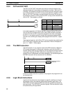
Note When displaying ladder diagrams with a GPC, a FIT, or LSS, a second bus
bar will be shown on the right side of the ladder diagram and will be con-
nected to all instructions on the right side. This does not change the ladder
diagram program in any functional sense. No conditions can be placed be-
tween the instructions on the right side and the right bus bar, i.e., all instruc-
tions on the right must be connected directly to the right bus bar. Refer to the
GPC
,
FIT
, or
LSS Operation Manual
for details.
The Ladder Diagram Section 4-3