


97
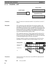
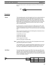
The values must be four-digit BCD in the range 0000 to 9999. Note that fail-
ure to enter BCD values will not activate the ERR flag. Always set a lower
limit which is less than the corresponding upper limit. MOV is useful in setting
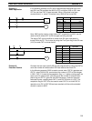
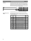
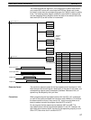
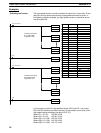
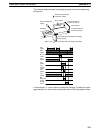
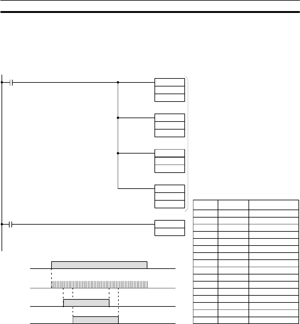
limits. The following ladder diagram shows the use of MOV for setting limits
and the associated timing diagram shows the state of the relevant bits of the
result word (IR 05) as the counter is incremented.
0000 LD 1813
0001 MOV(21)
# 0200
DM 32
0002 MOV(21)
# 1500
DM 33
0003 MOV(21)
# 0600
DM 34
0004 MOV(21)
# 2000
DM 35
0005 LD 0002
0006 HDM(61) 47
05
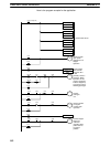
1813 (normally ON)
0002 (start input)
MOV(21)
#0200
DM 32
MOV(21)
#1500
DM 33
MOV(21)
#0600
DM 34
MOV(21)
#2000
DM 35
HDM(61) 47
05
Transfers
preset
value to
DM 32 to
35
Corresponding
result word is 05
Start input 0002
Output 0500
Output 0501
Count input 0000
200
600
1500
2000
Address Instruction Operands
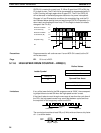
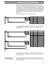
The maximum response speed of the high-speed counter hardware is 2 kHz.
Note however that the start signal, reset signal (in the case of soft reset), and
corresponding outputs are all processed by software. Because of this, re-
sponse may be delayed by the cycle time.
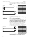
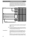
When programming the high-speed counter with the GPC, “00” is displayed
on each of the three lines below the instruction code (HDM(61)). Do not alter
the second and third lines; if they are not “00,” an error occurs when an at-
tempt is made to transfer the program from the GPC to the PC.
Do not program the high-speed counter between JMP and JME. The
high-speed counter can be programmed between IL and ILC. However, the
hard reset signal remains active, causing the corresponding output(s) to turn
ON or OFF, even when the IL condition is OFF.
Response Speed
Precautions
Timer and Counter Instructions Section 5-11