


31
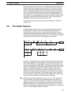
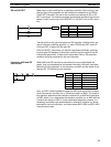
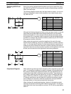
When two or more conditions lie on separate instruction lines running in par-
allel and then joining together, the first condition corresponds to a LOAD or
LOAD NOT instruction; the rest of the conditions correspond to OR or OR
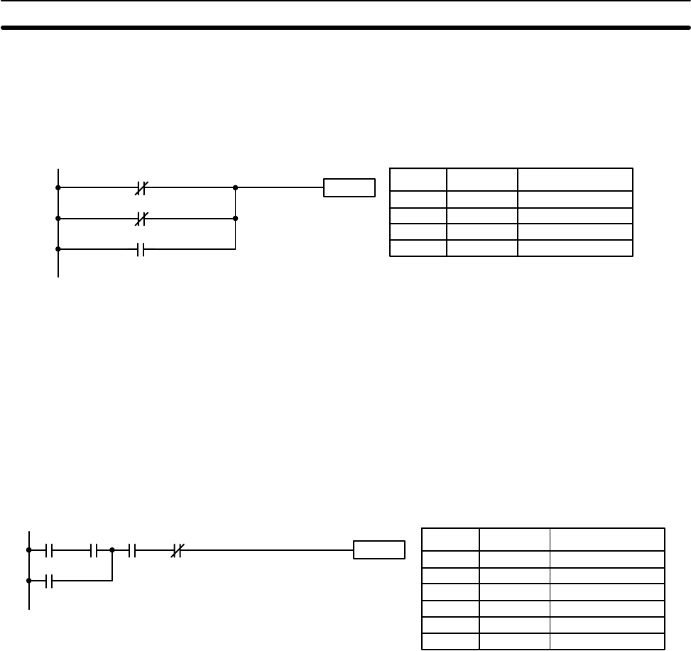
NOT instructions. The following example shows three conditions which corre-
spond in order from the top to a LOAD NOT, an OR NOT, and an OR instruc-
tion.
Instruction
0100
HR 000
0000
Address Instruction Operands
0000 LD 0000
0001 OR NOT 0100
0002 OR HR 000
0003 Instruction
The instruction at the right would have an ON execution condition when any
one of the three conditions was ON, i.e., when IR 0000 was OFF, when IR
0100 was OFF, or when HR 000 was ON.
OR and OR NOT instructions can also be considered individually, each tak-
ing the logical OR between its execution condition and the status of the OR
instruction’s operand bit. If either one of these were ON, an ON execution
condition would be produced for the next instruction.
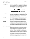
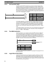
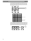
When AND and OR instructions are combined in more complicated dia-
grams, they can sometimes be considered individually, with each instruction
performing a logic operation on the execution condition and the status of the
operand bit. The following is one example.
Instruction
0002 00030000 0001
0200
Address Instruction Operands
0000 LD 0000
0001 AND 0001
0002 OR 0200
0003 AND 0002
0004 AND NOT 0003
0005 Instruction
Here, an AND is taken between the status of 0000 and that of 0001 to deter-
mine the execution condition for an OR with the status of 0200. The result of
this operation determines the execution condition for an AND with the status
of 0002, which in turn determines the execution condition for an AND with the
inverse of the status of 0003. In more complicated diagrams, however, it is
necessary to consider logic blocks before an execution condition can be de-
termined for the final instruction, and that’s where AND LOAD and OR LOAD
instructions are used.
OR and OR NOT
Combining AND and OR
Instructions
The Ladder Diagram Section 4-3