


60
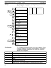
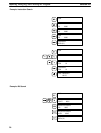
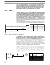
Here, 0500 will be turned ON for one cycle after 0000 goes ON. The next
time DIFU(13) 0500 is executed, 0500 will be turned OFF, regardless of the
status of 0000. With the DIFFERENTIATE DOWN instruction, 0501 will be
turned ON for one cycle after 0001 goes OFF (0501 will be kept OFF until
then) and will be turned ON the next time DIFD(14) is executed.
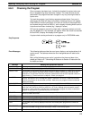
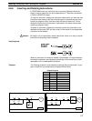
4-7-2 KEEP
The KEEP instruction is used to maintain the status of the operand bit based
on two execution conditions. To do this, the KEEP instruction is connected to
two instruction lines. When the execution condition at the end of the first in-
struction line is ON, the operand bit of the KEEP instruction is turned ON.
When the execution condition at the end of the second instruction line is ON,
the operand bit of the KEEP instruction is turned OFF. The operand bit for the
KEEP instruction will maintain its ON or OFF status even if it is located in an
interlocked section of the diagram and the execution condition for the INTER-
LOCK instruction is ON.
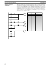
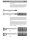
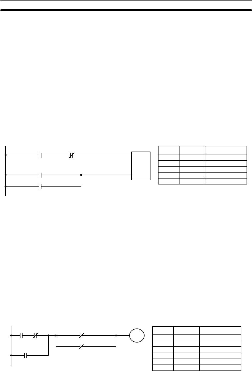
In the following example, HR 000 will be turned ON when 0002 is ON and
0003 is OFF. HR 000 will then remain ON until either 0004 or 0005 turns ON.
S:set
R: reset
KEEP(11)
HR 000
0002
0004
0003
0005
Address Instruction Operands
0000 LD 0002
0001 AND NOT 0003
0002 LD 0004
0003 OR 0005
0004 KEEP(11) HR 000
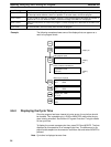
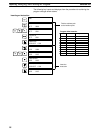
4-7-3 Self-maintaining Bits (Seal)
Although the KEEP instruction can be used to create self maintaining bits, it
is sometimes necessary to create self maintaining bits in another way so that
they can be turned OFF when in an interlocked section of a program.
To create a self maintaining bit, the operand bit of an OUTPUT instruction is
used as a condition for the same OUTPUT instruction in an OR setup so that
the operand bit of the OUTPUT instruction will remain ON or OFF until
changes in other bits occur. At least one other condition is used just before
the OUTPUT instruction to function as a reset. Without this reset, there would
be no way to control the operand bit of the OUTPUT instruction.
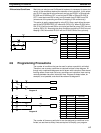
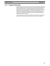
The above diagram for the KEEP instruction can be rewritten as shown be-
low. The only difference in these diagrams would be their operation in an in-
terlocked program section when the execution condition for the INTERLOCK
instruction was ON. Here, just as in the same diagram using the KEEP in-
struction, two reset bits are used, i.e., HR 000 is turned OFF by turning ON
both 0004 and 0005.
0002 0003
HR 000
HR 000
0004
0005
Address Instruction Operands
0000 LD 0002
0001 AND NOT 0003
0002 OR HR 000
0003 AND NOT 0004
0004 OR NOT 0005
0005 OUT HR 000
Controlling Bit Status Section 4-7