


24
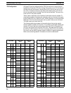
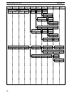
Once a TC number has been defined using one of these instructions, it can-
not be redefined elsewhere in the program using the same or a different in-
struction. If the same TC number is defined in more than one of these in-
structions or in the same instruction twice, an error will be generated during
the program check. There are no restrictions on the order in which TC num-
bers can be used.
Once defined, a TC number can be designated as an operand in one or more
instructions other than those listed above. When defined as a timer, a TC
number designated as an operand takes a TIM prefix. The TIM prefix is used
regardless of the timer instruction that was used to define the timer. Once
defined as a counter, the TC number designated as an operand takes a CNT
prefix. The CNT is also used regardless of the counter instruction that was
used to define the counter.
TC numbers can be designated for operands that require bit data or for oper-
ands that require word data. When designated as an operand that requires
bit data, the TC number accesses the completion flag of the timer or counter.
When designated as an operand that requires word data, the TC number ac-
cesses a memory location that holds the PV of the timer or counter.
TC numbers are also used to access the SV of timers and counters from a
Programming Device. The procedures for doing so from the Programming
Console are provided in
7-3 Monitoring Operation and Modifying Data.
The TC area retains the SVs of both timers and counters during power inter-
ruptions. The PVs of timers are reset when PC operation is begun and when
reset in interlocked program sections. Refer to
5-7 INTERLOCK AND INTER-
LOCK CLEAR - IL(02) and ILC(03)
for details on timer and counter operation
in interlocked program sections. The PVs of counters are not reset at these
times.
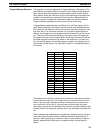
Note that in programming “TIM 00” is used to designate three things: the
TIMER instruction defined with TC number 00, the completion flag for this
timer, and the PV of this timer. The meaning in context should be clear, i.e.,
the first is always an instruction, the second is always a bit, and the third is
always a word. The same is true of all other TC numbers prefixed with TIM or
CNT. In explanations of ladder diagrams, the completion flag and PV ac-
cessed through a TC number are generally called the completion flag or the
PV of the instruction (e.g., the completion flag of TIM 00 is the completion
flag accessed through TC number 00, which has been defined using TIM).
When the RDM (REVERSIBLE DRUM COUNTER) is used, TC 46 is used as
the present value storage area of the counter and thus cannot be used for
any other purpose.
When the HDM (HIGH-SPEED DRUM COUNTER) is used, TC 47 is used as
the present value storage area of the counter and thus cannot be used for
any other purpose.
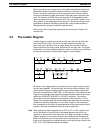
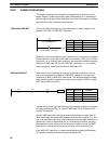
3-8 Temporary Relay (TR) Area
The TR area provides eight bits that are used only with the LD and OUT in-
structions to enable certain types of branching ladder diagram programming.
The use of TR bits is described in
Section 4 Writing and Inputting the Pro-
gram
.
TR addresses range from TR 0 though TR 7. Each of these bits can be used
as many times as required and in any order required as long as the same TR
bit is not used twice in the same instruction block.
Temporary Relay (TR) Area Section 3-8