


!
!
22
These clock pulse bits are often used with counter instructions to create tim-
ers. Refer to
5-11 Timer and Counter Instructions
for an example of this.
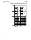
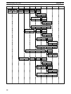
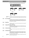
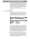
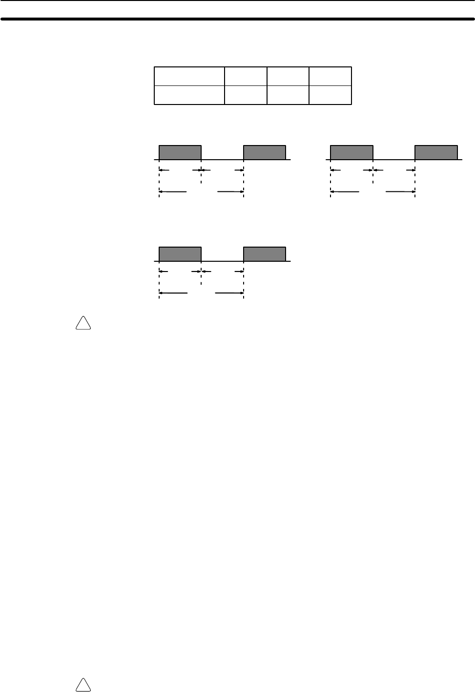
Pulse width 0.1 s 0.2 s 1.0 s
Bit 1900 1901 1902
Bit 1900
0.1-s clock pulse
0.1 s
.05 s .05 s
Bit 1901
0.2-s clock pulse
0.2 s
0.1 s 0.1 s
Bit 1902
1.0-s clock pulse
1.0 s
0.5 s 0.5 s
Caution Because the 0.1-second clock pulse bit has an ON time of 50 ms, the CPU may
not be able to accurately read the pulses if program execution time is too long.
3-4-5 Error Flag (ER)
SR bit 1903 turns ON when the results of an arithmetic operation is not out-
put in BCD or the value of the BIN data processed by the BIN to BCD or BCD
to BIN conversion instruction exceeds 9999. When the ER flag is ON the cur-
rent instruction is not executed.
3-4-6 Step Flag
SR bit 1811 turns ON for one cycle when single-step execution is started with
the STEP instruction.
3-4-7 Always OFF, Always ON Flags
SR bits 1812 and 1814 are always OFF and 1813 is always ON. By connect-
ing these bits to external indicating devices such as a LED they can be used
to monitor the PC’s operating status.
3-4-8 First Cycle Flag
SR bit 1815 turns ON when program execution starts and turns OFF after
one cycle.
3-4-9 Arithmetic Flags
The following flags are used in data shifting, arithmetic calculation, and com-
parison instructions. They are generally referred to only by their two-letter
abbreviations. Refer to
5-12 Data Shifting
,
5-14 DATA COMPARE - CMP(20)
and
5-16 BCD Calculations
for details.
Caution These flags are all reset when END is executed, and therefore cannot be moni-
tored from a Programming Device.
Special Relay (SR) Area Section 3-4