Software Developer’s Manual 263
Register Descriptions
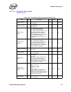
13.4.7.1.14 PHY Specific Status Register
PSSTAT (17d; R)
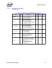
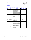
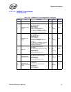
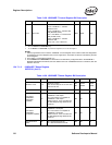
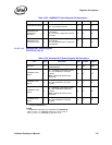
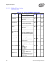
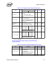
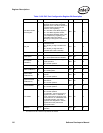
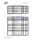
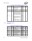
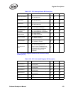
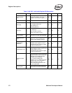
Table 13-33. PHY Specific Status Register Bit Description
Field Bit(s) Description Mode HW Rst SW Rst
Jabber (real time) 0
1b = Jabber.
0 = No jabber.
RO 0b Retain
Polarity (real time) 1
1b = Reversed.
0b = Normal.
RO 0b 0b
Receive Pause
Enable
2
1b = Receive pause enabled.
0b = Receive pause disabled.
The Receive Pause Enable bit is valid
only after the Speed and Duplex
Resolved bit (11) is set. This occurs
when Auto-Negotiation is completed or
Auto-Negotiation is disabled.
This is a reflection of the MAC pause
resolution.
RO 0b 0b
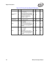
Transmit Pause
Enabled
3
1b = Transmit pause enabled.
0b = Transmit pause disabled.
The Transmit Pause Enable bit is valid
only after the Speed and Duplex
Resolved bit (11) is set. This occurs
when Auto-Negotiation is completed or
Auto-Negotiation is disabled.
RO 0b 0b
Energy Detect Status 4
0b = Active
1b = Sleep
RO 0b 0b
Downshift Status 5
1b = Downshift.
0b = No Downshift.
RO 0b 0b
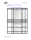
MDI Crossover
Status
6
1b = MDI-X.
0b = MDI.
The MDI Crossover Status bit is valid
only after the Speed and Duplex
Resolved bit (11) is set. This occurs
when Auto-Negotiation is completed or
Auto-Negotiation is disabled.
RO 0b 0b
Cable Length
(100/1000 modes
only)
9:7
000b = < 50 m.
001b = 50 − 80 m.
010b = 80 − 110 m.
011b = 110 − 140 m.
100b = >140 m.
Cable length measurement is only a
rough estimate. The actual value
depends on the attenuation of the cable,
output levels of the remote transceiver,
connector impedance, etc.
RO 000b 000b
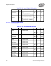
Link (real time) 10
1b = Link up.
0b = Link down.
RO 0b 0b


