116 Software Developer’s Manual
EEPROM Interface
5.6.27 IPv4 Address (Words 15h - 16h
1
and 25h - 26h)
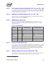
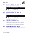
The following table lists the initial values for the IPv4 addresses.
Note: Since the 82546GB/EB is a dual-port device, the IPv4 Address in 15h-16h corresponds to LAN B,
and the IPv4 Address in 25h-26h corresponds to LAN A.
5.6.28 IPv6 Address (words 17h - 1Eh
1
and 27h - 2Eh)
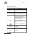
The following table lists the initial values for the IPv6 addresses.
Note: Since the 82546GB/EB is a dual-port device, the IPv6 Address in 17h-1Eh corresponds to LAN B,
and the IPv6 Address in 27h-2Eh corresponds to LAN A.
5.6.29 LED Configuration Defaults (Word 2Fh)
2
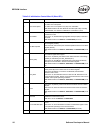
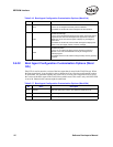
This EEPROM word specifies the hardware defaults for the LEDCTL register fields controlling the
LED0/(LINK_UP#) and LED2/LINK100 output behaviors. Refer to Table 13-60 for the LED
Control bit descriptions and Table 13-61 for the Mode Encodings.
Note: A value of 0602h is used to configure default hardware LED behavior equivalent to 82544-based
Copper adapters (LED0/LINK_UP#, LED1/ACTIVITY# (blinking), LED2/LINK100#, and
LED3/LINK1000#).
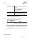
5.6.30 Boot Agent Main Setup Options (Word 30h)
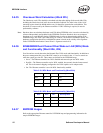
The boot agent software configuration is controlled by the EEPROM with the main setup options
stored in word 30h. These options are those that can be changed by using the Control-S setup menu
or by using the IBA Intel Boot Agent utility.
Note: The 82541ER does not support the Intel Boot Agent functionality.
1. Applicable to the 82546GB/EB only.
Table 5-13. IPv4 Addresses
Bit Name Description
31:0 IPv4 Address
The initial value of IPv4 Address Table entry 0. (IP4AT[0]).
Refer to the EEPROM Address Map listed in Table 5-2 for an indication
of how the bytes are stored.
Table 5-14. IPv6 Address
Bit Name Description
127:0 IPv6 Address
The initial value of IPv6 Address Table entry 0. (IP6AT[0])
Refer to the EEPROM Address Map listed in Table 5-2 for an indication
of how the bytes are stored.
2. Not applicable to the 82544GC/EI.


