


Intel
®
855GME and Intel
®
852GME Thermal Design Guide for Embedded Applications 25
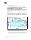
Temperature Measurement Metrology
Temperature Measurement Metrology 6
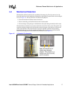
6.1 Case Temperature Measurements
Intel has established guidelines for the proper techniques to be used when measuring chipset MCH
case temperature. Section 7.3 contains information on running an application program that
emulates anticipated TDP.
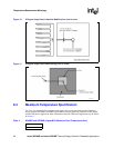
The surface temperature at the geometric center of the die corresponds to the maximum Tcase.
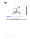
6.2 0 Degree Angle Attach Methodology
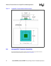
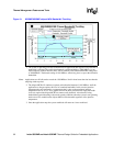
1. Mill a 3.3 mm (0.13”) diameter hole centered on bottom of the heatsink base (see Figure 5).
The milled hole should be approximately 1.5 mm (0.06”) deep.
2. Mill a 1.3 mm (0.05”) wide slot, 0.5 mm (0.02”) deep, from the centered hole to one edge of
the heatsink. The slot should be in the direction parallel to the heatsink fins (see Figure 16 and
Figure 17).
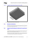
3. Attach thermal interface material (TIM) to the bottom of the heatsink base.
4. Cut out portions of the TIM to make room for the thermocouple wire and bead. The cutouts
should match the slot and hole milled into the heatsink base.
5. Attach a 36 gauge or smaller calibrated K-type thermocouple bead or junction to the center of
the top surface of the die using a high thermal conductivity cement. During this step, make
sure there is no contact between the thermocouple cement and the heatsink base because any
contact will affect the thermocouple reading. It is critical that the thermocouple bead makes
contact with the die (see Figure 17).
6. Attach heatsink assembly to the MCH and route the thermocouple wires our through the
milled slot.