


14 Intel
®
855GME and Intel
®
852GME Thermal Design Guide for Embedded Applications
Reference Thermal Solution for 1U Applications
Reference Thermal Solution for 1U
Applications 4
4.1 Applications
The thermal solution referenced in this chapter is valid for both the 855GME and 852GME when
the system allows for upwards of 1U (1.75” chassis) in z-height.
Note: Many boundary conditions may permit the 855GME MCH heatsink to be packaged without a
thermal solution. The 852GME will require a heatsink in most configurations. See Section 3 for
computational fluid dynamics (CFD) modeling where specific boundary conditions are analyzed.
The reference thermal solution is capable of adequately cooling the 855GME or 852GME chipset
MCHs at all boundary conditions referenced in Section 3.4.
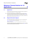
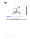
4.2 Required Volumetric Keepout
The 1U thermal solution will require a volumetric keepout region above the chipset MCH. See
Figure 7 for a detailed side and top view of the keepout.
Appendix B, “Mechanical Drawings” contains a detailed board keep-out restriction for the
heatsink and mounting clips.
Note that the 1U reference thermal solution for embedded applications is exactly the same as that
referenced in the thermal design guide for the Intel® 845G chipset MCH. See Table 1 for location
of the Intel® 845G Chipset MCH Thermal Design Guide.