


18 Intel
®
855GME and Intel
®
852GME Thermal Design Guide for Embedded Applications
Reference Thermal Solution for 1U Applications
4.5 Thermal Interface Material (TIM) and Thermal Bond
Line
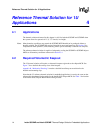
A thermal interface material (TIM) is used to provide improved conductivity between the die and
heatsink. The reference thermal solution uses Chomerics* T-710, 0.127 mm (0.005”) thick,
12.7 mm x 12.7 mm (0.5” x 0.5”).
The thickness of the bond line between the heatsink and die is critical to the thermal performance
of the TIM. The bond line thickness is dependent on the pressure between the heatsink and the die.
The clip retention mechanism is used to generate the pressure required to ensure the thermal
performance required. The generic clip frame and lever design generates more than 50-psi
pressure.
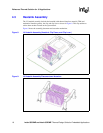
4.6 Solder Joint Protection
The generic clip design uses mechanical preload on the package to protect the solder joint against
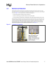
damage under mechanical shock. The design features a rotating cam (see Figure 12) that generates
substantial preload between the heatsink and package. The cam has a levered handle that provides
a mechanical advantage during installation.
The preload serves to compress the solder ball array between the package and the motherboard.
The compression in the solder balls delays the onset of the tensile load under critical shock
conditions, and the magnitude of the maximum tensile load is thereby reduced. In this manner, the
critical solder balls are protected from tensile loading that may cause damage to the solder joint.
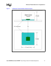
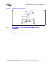
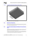
Figure 11. 1U Heatsink Clip Lateral Retention Tab Feature