Intel
®
855GME and Intel
®
852GME Thermal Design Guide for Embedded Applications 23
Reference Thermal Solution for CompactPCI* and Blade Applications
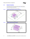
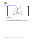
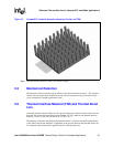
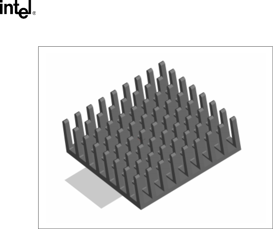
Note: Thermal Interface Material (TIM) is not shown in picture.
5.5 Mechanical Retention
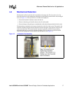
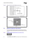
The heatsink is affixed to the die with an adhesive tape thermal interface material. This retention
scheme does not require board modifications and can be incorporated at any point in the design
cycle, assuming the z-height requirement is met.
5.6 Thermal Interface Material (TIM) and Thermal Bond
Line
A thermal interface material (TIM) is used to provide improved conductivity between the die and
heatsink. The reference thermal solution uses Chomerics* T411 adhesive tape thermal interface
material, 15 mm x 15 mm x 0.254 mm (0.59” x 0.59” x .01”).
The thickness of the bond line between the heatsink and die is critical to the thermal performance
of the TIM. The bond line thickness is dependent on the pressure between the heatsink and the die.
It is imperative that the heatsink is applied to the die with adequate force.
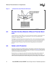
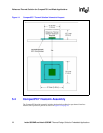
Figure 15. CompactPCI* Heatsink Assembly (Heatsink, Pull-tab, and TIM)


