


12 Intel
®
855GME and Intel
®
852GME Thermal Design Guide for Embedded Applications
Computational Fluid Dynamics (CFD) Modeling
presented the copper content is assumed to be 10 percent of the overall volume of the
motherboard.
4. Board-to-board spacing of 0.8”, consistent with the CompactPCI* specification.
5. Tj,max for the 855GME and 852GME chipset MCHs is 110 °C.
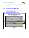
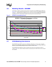
3.5 Modeling Results – 855GME MCH
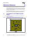
Some boundary conditions evaluated will necessitate a heatsink for the 855GME chipset MCH.
See Figure 5 for a graph of junction temperature (Tj) vs. airflow (in linear feet per minute) for
various local ambient temperature conditions. A heatsink will be needed in all cases where the Tj
of the 855GME chipset MCH die is greater than 110 °C.
Figure 5. 855GME MCH (4.3W) Junction Temperatures vs. Airflow
855GME (4.3W) Junction Temperatures vs. Airflow
at Various Local Ambient Temperatures
80
90
100
110
120
130
140
50 100 150 200 250 300 350 400 450 500
Airflow (LFM)
Tj (deg C)
40 C
45 C
50 C
55 C
60 C
T
j max = 110
°
C
Heatsink
Required