


28
|
Installation
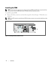
NOTE: The pins must be open to keep the UPS running. If the UPS shuts down because the REPO connector
pins are shorted, restart the UPS by re-opening the REPO connector pins and turning on the UPS manually.
Maximum resistance in the shorted loop is 10 ohm.
NOTE: Always test the REPO function before applying your critical load to avoid accidental load loss.
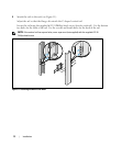
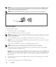
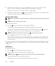
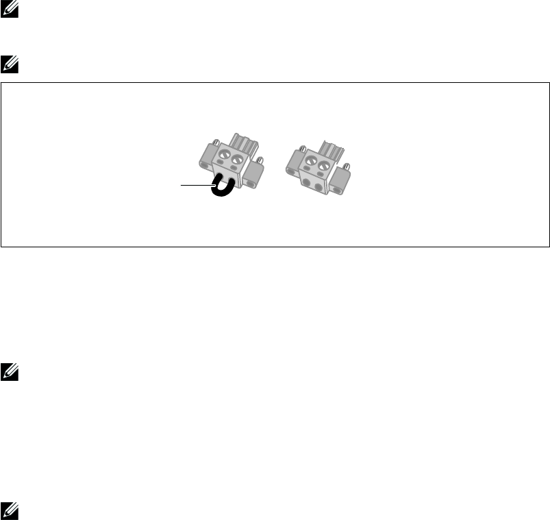
Remove Jumper if
installed
Figure 18. REPO Connector
To install the REPO switch:
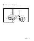
1 Verify that the UPS is off and unplugged.
2 Remove the REPO connector from the accessory kit.
NOTE:
Verify that there is no jumper installed in the REPO connector. If a jumper is installed, remove it before
connecting to the REPO port.
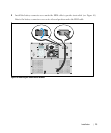
3 Connect the REPO connector to the REPO port labeled “IN” on the UPS rear panel.
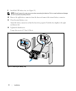
4 Optional. If you are daisy-chaining the REPO function with another UPS, you can shut down the
entire system using a single switch.
Connect the second REPO connector to the REPO port labeled “OUT.”
NOTE:
A separate contact must simultaneously cause UPS input AC power to be removed.
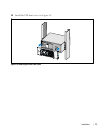
5 Connect the switch or circuit to the REPO connector on the UPS rear panel using insulated
0.75 mm
2
–0.5 mm
2
(18–20 AWG) wire.
Optional. If you are daisy-chaining the REPO function with another UPS, connect the REPO port
labeled “OUT” to the REPO port labeled “IN” on the next UPS. Continue for each UPS. On the
last UPS in the daisy-chain, connect a REPO connector (without a jumper) in the REPO port
labeled “OUT.”
6 Verify that the externally-connected REPO switch is not activated to enable power to the UPS
output receptacles.
7 Continue to the following section, “UPS Initial Startup.”