


1-9
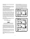
REMOTE OPERATING MODES
Remote operatin
g
modes discussed below are remote volta
g
e
sensin
g
and remote volta
g
e pro
g
rammin
g
. You can set up the unit
for remote operatin
g
modes b
y
chan
g
in
g
the settin
g
s of the rear
panel switch and connectin
g
the leads from the rear panel termi-
nals to the load or the external volta
g
e. Solid conductors of 0.75
to 1.5 mm
2
can be connected to the rear panel terminals b
y
sim-
pl
y
push fittin
g
. Thinner wires or conductors are inserted into the
connection space after depressin
g
the oran
g
e openin
g
lever.
Turn off the suppl
y
while makin
g
chan
g
es to rear panel
switch settin
g
s or connections. This avoids the possibilit
y
of dama
g
e to the load and OVP shutdown from unin-
tended output.
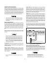
Remote Voltage Sensing
Remote volta
g
e sensin
g
is used to maintain
g
ood re
g
ulation at
the load and reduce the de
g
radation of re
g
ulation that would
occur due to the volta
g
e drop in the leads between the power
suppl
y
and the load. B
y
connectin
g
the suppl
y
for remote volta
g
e
sensin
g
, volta
g
e is sensed at the load rather than at the suppl
y
's
output terminals. This will allow the suppl
y
to automaticall
y
com-
pensate for the volta
g
e drop in the load leads and improve re
g
ula-
tion.
When the suppl
y
is connected for remote sensin
g
, the OVP circuit
senses the volta
g
e at the sense leads and not the main output
terminals.
Remote volta
g
e sensin
g
compensates for a volta
g
e drop of
up to 0.5 V in each load, and there ma
y
be up to a 0.1 V
drop between the output terminal and the internal sensin
g
resistor, at which point the OVP circuit is connected. There-
fore, the volta
g
e sensed b
y
the OVP circuit could be as
much as 1.1 V more than the volta
g
e bein
g
re
g
ulated at the
load. It ma
y
be necessar
y
to re-adjust the OVP trip volta
g
e
when usin
g
remote sensin
g
.
CV Re
g
ulation.
Notice that an
y
volta
g
e drop in the sense leads
adds directl
y
to the CV load re
g
ulation. In order to maintain the
specified performance, keep the sense lead resistance to 0.5
ohms per lead or less.
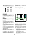
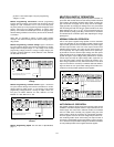
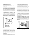
Remote Sensin
g
Connections.
Remote sensin
g
requires
chan
g
in
g
settin
g
s of the rear panel switch and connectin
g
the
load leads from + and - output terminals to the load and connect-
in
g
the sense leads from the +S and -S terminals to the load as
shown in Fi
g
ure 5.
Observe polarit
y
when connectin
g
the sensin
g
leads to
the load.
Output Noise.
An
y
noise picked up on the sense leads will
appear at the suppl
y
's output volta
g
e and ma
y
de
g
rade CV load
re
g
ulation. Twist the sense leads to minimize the pickup of exter-
nal noise and run them parallel and close to the load leads. In
nois
y
environments, it ma
y
be necessar
y
to shield the sense
leads. Ground the shield at the power suppl
y
end onl
y
. Do not use
the shield as one of the sensin
g
conductors.
Stability.
When the suppl
y
is connected for remote sensin
g
, it is
possible for the impedance of the load wires and the capacitance
of the load to form a filter, which will become part of the suppl
y
's
CV feedback loop. The extra phase shift created b
y
this filter can
de
g
rade the suppl
y
's stabilit
y
and can result in poor transient
response performance or loop stabilit
y
. In extreme cases, it can
cause oscillations. Keep the leads as short as possible and twist
the leads of the load to eliminate the load lead inductance and
keep the load capacitance as small as possible.The load leads
should be of the lar
g
est diameter practical, heav
y
enou
g
h to limit
the volta
g
e drop in each lead to 0.5 volts.
The sense leads are part of the suppl
y
's pro
g
rammin
g
feedback
control loop. Accidental open-connections of sense or load leads
durin
g
remote sensin
g
operation have various unwanted effects.
Provide secure, permanent connections-especiall
y
for the sense
leads.
Fi
g
ure 5. Remote Volta
g
e Sensin
g
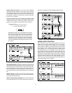
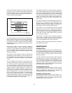
Remote Analog Voltage Programming
Remote analo
g
volta
g
e pro
g
rammin
g
permits control of the re
g
u-
lated output volta
g
e or current b
y
means of a remotel
y
varied volt-
a
g
e. The pro
g
rammin
g
(external) volta
g
e should not exceed 10
volts. The stabilit
y
of the pro
g
rammin
g
volta
g
es directl
y
affects
the stabilit
y
of the output. The volta
g
e control on the front panel is
disabled durin
g
remote analo
g
pro
g
rammin
g
.
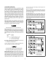
The suppl
y
includes clamp circuits to prevent it from
suppl
y
in
g
more than about 120% of rated output volta
g
e
or current when the remote pro
g
rammin
g
volta
g
e is
g
reater than 10 Vdc. Do not intentionall
y
operate the sup-
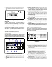
MASTER
SLAVE
CV CC SENSE
LOCAL
REMOTE
OUT
+S
-S
+
_
CV CC
VREF
A1 A2 A3 A4 A5
+
+
M/S 1 M/S 2
_
_
+
_
pq vg\BvBBBBB
nqcf