


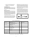

1-12
AUTO-SERIES OPERATION
Auto-series operation permits equal or proportional volta
g
e
sharin
g
, and allows control of output volta
g
e from one master
unit. The volta
g
e of the slaves is determined b
y
the settin
g
of
the front panel VOLTAGE control on the master and volta
g
e
divider resistor. The master unit must be the most positive sup-
pl
y
of the series. The output CURRENT controls of all series
units are operative and the current limit is equal to the lowest
settin
g
. If an
y
output CURRENT controls are set too low, auto-
matic cross over to constant current operation will occur and the
output volta
g
e will drop. Fi
g
ure 12 and Fi
g
ure 13 show the rear
panel switch settin
g
s and terminal connections for Auto-series
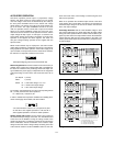
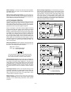
operation of two supplies and three supplies. This mode can
also
g
ive ±volta
g
e trackin
g
operation of two supplies with two
separate loads.
Mixed model numbers ma
y
be emplo
y
ed in auto-series combi-
nation without restriction, provided that each slave is specified as
bein
g
capable of auto-series operation. If the master suppl
y
is set
up for constant current operation, then the master-slave combina-
tion will act as a composite constant current source.
Total output volta
g
e to
g
round must not exceed 240 Vdc.
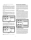
Determinin
g
Resistors.
External resistors control the fraction (or
multiple) of the master unit's volta
g
e settin
g
that is supplied from
the slave unit. Notice that the percenta
g
e of the total output volt-
a
g
e contributed b
y
each suppl
y
is independent of the ma
g
nitude
of the total volta
g
e. For two units in auto-series the ratio of R1 to
R2 is
(R1+R2)/R1 = (Vo/Vm)
R2/R1 = (Vs/Vm)
Where Vo = auto-series volta
g
e = Vs + Vm
Vm = master unit's output volta
g
e
Vs = slave unit's output volta
g
e
For example, usin
g
the E3617A as a slave unit and puttin
g
R2=50
kΩ (1/4 watt), then from the above equations,
R1 = R2(Vm/Vs) = 50(Vm/Vs) kΩ
In order to maintain the temperature coefficient and stabilit
y
perfor-
mance of the suppl
y
, choose stable, low noise resistors.
It is recommended to connect a 0.1 µF capacitor in paral-
lel with R2 in two supplies operation or R2 and R4 in
three supplies operation to ensure the stable operation.
Settin
g
Volta
g
e and Current.
Use the master unit's controls to
set the desired output volta
g
e and current. The VOLTAGE control
of the slave unit is disabled. Turnin
g
the volta
g
e control of the
master unit will result in a continuous variation of the output of the
series combination, with the contribution of the master's output
volta
g
e to that of the slave's volta
g
e alwa
y
s remainin
g
in the ratio
of the external resistors. Set the CURRENT control of slave unit
above the master unit's current settin
g
to avoid havin
g
the slave
switch to CC operation.
When in CC operation the combined output current is the same
as the master unit's current settin
g
, and when in CV operation the
combined output volta
g
e is the sum of the master unit's and the
slave unit's output volta
g
es.
Overvolta
g
e Protection.
Set the OVP shutdown volta
g
e in each
unit so that it shuts down at a volta
g
e hi
g
her than its output volta
g
e
durin
g
auto-series operation. When a master unit shuts down, it pro-
g
rams an
y
slave units to zero output. When a slave unit shuts down,
it shuts down onl
y
itself (and an
y
slaves below it in the stack). The
master (and all slaves above the shut-down slave) continues to sup-
pl
y
output volta
g
e.
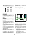
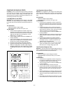
Fi
g
ure 12. Auto-Series Operation of Two Supplies
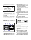
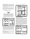
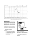
Fi
g
ure 13. Auto-Series Operation of Three Supplies
MASTER
SLAVE
CV CC SENSE
LOCAL
REMOTE
OUT
+S -S
+
_
CV CC
VREF
A1 A2 A3 A4 A5
+
+
M/S 1 M/S 2
__
MASTER
SLAVE
CV CC SENSE
LOCAL
REMOTE
OUT
+S
-S
+
_
CV CC
VREF
A1 A2 A3 A4 A5
+
+
M/S 1 M/S 2
_
_
MASTER POWER SUPPLY
LOAD
SLAVE POWER SUPPLY
R1 R2
MASTER
SLAVE
CV CC SENSE
LOCAL
REMOTE
OUT
+S
-S
+
_
CV CC
VREF
A1 A2 A3 A4 A5
+
+
M/S 1 M/S 2
__
MASTER POWER SUPPLY
LOAD
MASTER
SLAVE
CV CC SENSE
LOCAL
REMOTE
OUT
+S
-S
+
_
CV CC
VREF
A1 A2 A3 A4 A5
+
+
M/S 1 M/S 2
__
SLAVE POWER SUPPLY(S1)
MASTER
SLAVE
CV CC SENSE
LOCAL
REMOTE
OUT
+S
-S
+
_
CV CC
VREF
A1 A2 A3 A4 A5
+
+
M/S 1 M/S 2
__
SLAVE POWER SUPPLY(S2)
R1 R2
R3 R4
Vo=Vm(1+
R2
R1
R2
R1
+
R4
R3
)
Where Vo = Auto-Series volta
g
e = Vm + Vs1 + Vs2
Vm = master unit's output volta
g
e
Vs1 = slave(S1) unit's output volta
g
e
Vs2 = slave
(
S2
)
unit's output volta
g
e