


A-1
SERVICE INFORMATION
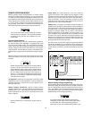
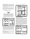
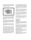
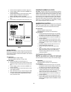
Figure A-1. Block Diagram
PRINCIPLES OF OPERATION
(Block Diagram Overview)
Throughout this discussion, refer to both the block diagram of
Figure A-1 and the schematic diagrams at the rear of the
manual. The input ac line voltage is first applied to the prereg-
ulator which operates in conjunction with the SCR control cir-
cuit (preregulator control circuit) to rectify the tap switched AC
voltage. This preregulator minimizes the power dissipated in
the series regulating elements by controlling the dc level
across the input filter capacitor, depending on the output volt-
age.
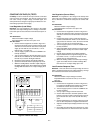
To achieve this, tap switching is accomplished by four SCRs
and one bridge diode (CR10, CR12, CR15, CR18 and CR13)
and the SCR control circuit. By selecting different SCR firing
combinations from SCR control circuit, these circuits allow the
input capacitors (C7 and C8) to charge to one of four discrete
voltage levels, depending on the output voltage required.
The main secondary winding of the power transformer has
three sections (N1, N2, and N3), each of which has a different
turns ratio with respect to the primary winding. At the begin-
ning of each half-cycle of the input ac, the control circuit
determines whether one pair, both or none of the SCR will be
fired. If neither SCR is fired, the bridge diode (CR13) receives
an ac input voltage that is determined by N1 turns and the
input capacitors charge to a corresponding level. If SCR
CR15 and CR18 are fired, input capacitors charge to the volt-
age determined by N1+N2 turns. Similarly, if CR10 and CR12
are fired the capacitors are charged by N1 + N3. Finally, if all
SCRs are fired simultaneously, input capacitors charge to its
highest voltage level determined by N1 + N2 + N3 turns.
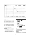
The SCR control circuit determines which SCRs are to be
fired by monitoring the output voltage and comparing these
values against a set of three internally derived reference lev-
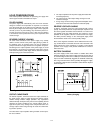
els. These three reference levels are translated into boundary
lines to allow the output characteristic to be mapped into four
operating regions (Figure A-2). The boundary lines, which are
invisible to the user, are divided into four operating regions
(V1, V2, V3, and V4) to minimize the power dissipation in the