


A-8
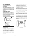
Ammeter and CC Set Calibration
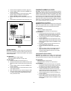
To calibrate ammeter and CC set, proceed as follows:
a. Connect test setup on Fi
g
ure A-9.
b. Turn VOLTAGE and CURRENT control full
y
clock-
wise.
c. Turn on the suppl
y
and to calibrate ammeter adjust
R5 on the displa
y
board until front panel AMPS dis-
pla
y
reads exactl
y
DVM value divided b
y
Rs.
d. To calibrate CC Set adjust R69 on the main board
until front panel AMPS displa
y
reads exactl
y
DVM
value divided b
y
Rs while depressin
g
OVP/CC Set
switch.
Voltmeter and OVP Set Calibration
To calibrate voltmeter and OVP set, proceed as follows:
a. Disconnect Rs from test setup on Fi
g
ure A-9 and
connect DVM across output terminal of the suppl
y
.
b. Turn on the suppl
y
.
c. To calibrate voltmeter for E3614A, adjust R16 on the
displa
y
board until front panel VOLTS displa
y
reads
exactl
y
DVM value. To calibrate voltmeter for
E3615A, E3616A and E3617A set the output volta
g
e
below 18V (ex, 15V), and adjust R16 on the displa
y
board until front panel VOLTS displa
y
reads exactl
y
DVM value. Next, set the output volta
g
e above 20V
(ex, 21V) and adjust R17 on the displa
y
board until
front panel VOLTS displa
y
reads exactl
y
DVM value.
d. To calibrate OVP Set, turn down the OVP Adjust
screwdriver control on the front panel slowl
y
until the
OVP circuit trips. Record the output volta
g
e when the
OVP trip occurs. Then adjust R97 on the main board
until front panel VOLTS displa
y
reads exactl
y
OVP
trip volta
g
e while depressin
g
OVP/CC Set switch.
TROUBLESHOOTING
Before attemptin
g
to troubleshoot the power suppl
y
, ensure
that the fault is with the suppl
y
and not with an associated cir-
cuit. The performance test enables this to be determined
without havin
g
to remove the covers from the suppl
y
.
The applicable test points are identified b
y
encircled
numbers on the schematic dia
g
rams at the rear of the
manual, Fi
g
ure A-10, Fi
g
ure A-11, Fi
g
ure A-12, and
Fi
g
ure 13.
A
g
ood understandin
g
of the principles of operation is a help-
ful aid in troubleshootin
g
, and it is recommended that princi-
ples of operation in this manual be reviewed before
attemptin
g
to troubleshoot the suppl
y
. Once the principles of
operation are understood, refer to the overall troubleshootin
g
procedures para
g
raph to locate the s
y
mptom and probable
cause.
Once the defective component has been located (b
y
means
of visual inspection or trouble anal
y
sis) replace it and recon-
duct the performance test. After a component is replaced,
perform the meter calibration.
Overall Troubleshooting Procedure
To locate the cause of trouble follow steps 1, 2, and 3 in
sequence. Before attemptin
g
overall troubleshootin
g
, ensure
that the rear-panel switches M/S 1 and M/S 2 be set to MAS-
TER position and CV, CC, and SENSE to LOCAL position.
1. Check that input power is available, and check the
power cord and rear panel line fuse. When replacin
g
line fuse, be certain to select fuse of proper ratin
g
for
line volta
g
e bein
g
used.
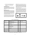
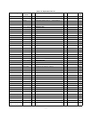
2. In almost all cases, the trouble source can be caused
b
y
the dc bias or reference volta
g
es; thus, it is a
g
ood
practice to check volta
g
es in Table A-2 before pro-
ceedin
g
with step 3.
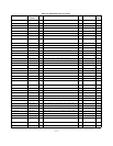
3. Disconnect the load and examine Table A-3 to deter-
mine
y
our s
y
mptom, then check the probable cause.
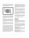
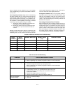
Reference and Bias Circuit
a. Make an ohmmeter check to be certain that neither
the positive and ne
g
ative output terminal is
g
rounded.
b. Turn front panel VOLTAGE and CURRENT controls
full
y
clockwise.
c. Turn on power suppl
y
(no load connected).
d. Proceed as instructed in Table A-2.
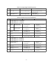
Regulating Loop Troubles
If the volta
g
es in Table A-2 have been checked to eliminate
the reference and bias circuits as a source of trouble; the mal-
function is caused b
y
either the series re
g
ulator or prere
g
ula-
tor feedback loop. Because the interaction between these two
loops makes lo
g
ical troubleshootin
g
difficult, the followin
g
steps help
y
ou to locate the source of troubles in these two
feedback loops. Once the trouble has been located to one of
the feedback loops, the operation of either loop can be ana-
l
y
zed independentl
y
. This method should be followed when-
ever a low output volta
g
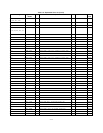
e condition exists. Notice that
troubleshootin
g
can proceed directl
y
as described in Table A-
4 whenever a hi
g
h output volta
g
e condition exists.
1. Turn on the power suppl
y
with full load connected
and increase output volta
g
e b
y
turnin
g
up the front
panel volta
g
e control. The output volta
g
e is clamped
and CV indicator is turned off at some output volta
g
e
(below full rated output volta
g
e). If this is the case,
the series re
g
ulator feedback loop is operatin
g
normall
y
and the trouble condition is probabl
y
due to
a defect in the prere
g
ulator feedback loop (refer to
Table A-6). If the output volta
g
e remains in low sta
g
e,
and var
y
in
g
the front panel volta
g
e control has little or
no effect, then the trouble is probabl
y
in the series
re
g
ulator feedback loop. Refer to Table A-5.
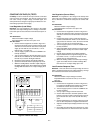
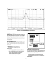
2. Measure the volta
g
e between TP2 and TP1 (shown
on the schematic dia
g
ram at the rear of the manual)
with full load with oscilloscope while increasin
g
the
output volta
g
e from 0 to full rated volta
g
e. The volt-
a
g
e measured has step chan
g
es three times durin
g
0
to full output volta
g
e swin
g
. If this is the case, prere
g
-
ulator feedback loop is operatin
g
normall
y
. If this is
not the case, the trouble is probabl
y
in the prere
g
ula-
tor feedback loop. Refer to Table A-6.