


1-4
GENERAL INFORMATION
INTRODUCTION
This manual describes all models in the Agilent E361xA 60W
Bench Power Supply family and unless stated otherwise, the
information in this manual applies to all models.
SAFETY REQUIREMENTS
This product is a Safety Class I instrument, which means
that it is provided with a protective earth ground terminal.
This terminal must be connected to an ac source that has a
3-wire ground receptacle. Review the instrument rear panel
and this manual for safety markings and instructions before
operating the instrument. Refer to the Safety Summary page
at the beginning of this manual for a summary of general
safety information. Specific safety information is located at
the appropriate places in this manual.
This power supply is designed to comply with the following
safety and EMC(Electromagnetic Compatibility) require-
ments:
nIEC 348: Safety Requirements for Electronic Measuring
Apparatus
nIEC 1010-1/EN 61010: Safety Requirements for Electrical
Equipment for Measurement, Control, and Laboratory Use
nCSA C22.2 No.231: Safety Requirements for Electrical and
Electronic Measuring and Test Equipment
nUL 1244: Electrical and Electronic Measuring and Testing
Equipment.
nEMC Directive 89/336/EEC: Council Directive entitled
Approximation of the Laws of the Member States relating to
Electromagnetic Compatibility
nEN 55011(1991) Group 1, Class B/CISPR 11: Limits and
nMethods of Radio Interference Characteristics of
nIndustrial, Scientific, and Medical(ISM) Radio-Frequency
Equipment
nEN 50082-1(1991) /
IEC 801-2(1991):Electrostatic Discharge Requirements
IEC 801-3(1984):Radiated Electromagnetic Field
Requirements
IEC 801-4(1988):Electrical Fast Transient/Burst
Requirements
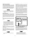
INSTRUMENT AND MANUAL IDENTIFICATION
A serial number identifies your power supply. The serial
number encodes the country of manufacture, the date of the
latest significant design change, and a unique sequential
number. As an illustration, a serial number beginning with
KR306 denotes a power supply built in 1993 (3=1 993,
4=1994, etc), 6th week manufacture in Korea(KR). The
remaining digits of the serial number are a unique, five-digit
number assigned sequentially.
If the serial number on your supply differs from that shown
on the title page of this manual, a yellow MANUAL
CHANGES sheet is supplied with this manual to explain
the difference between your instrument and the instrument
described by this manual. The change sheet may also con-
tain information for correcting errors in the manual.
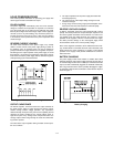
OPTIONS
Options OE3 and OE9 determine which line voltage is
selected at the factory. The standard unit is configured for 115
Vac ± 10%. For information about changing the line voltage
setting, see paragraph "INPUT POWER REQUIREMENTS",
page 1-6.
OE3: Input power, 230 Vac ± 10%, 47-63 Hz
OE9: Input power, 100 Vac ± 10%, 47-63 Hz
910: One additional manual
ACCESSORY
The accessory listed below may be ordered from your local
Agilent Technologies Sales Office either with the power sup-
ply or separately. (Refer to the list at the rear of the manual for
address.)
Agilent Part No.Description
5063-9240 Rack Kit for mounting one or two 3 1/2" high
supply in a standard 19" rack
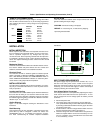
The rack mount kit is needed for rack mounting of all models
in the Agilent E361xA power supply because these supplies
have molded feet.
DESCRIPTION
This power supply is suitable for either bench or rack
mounted operation. It is a compact, well-regulated, Constant
Voltage/Constant Current supply that will furnish full rated
output voltage at the maximum rated output current or can be
continuously adjusted throughout the output range. The out-
put can be adjusted both locally from the front panel and
remotely by changing the settings of the rear panel switches
(See paragraph "REMOTE OPERATING MODES", page 1-9).
The models in this family offer up to 60 watts of output power,
with voltage up to 60 volts and current up to 6 amps as shown
in Table 1.
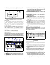
The front panel VOLTAGE control can be used to establish
the voltage limit when the supply is used as a constant cur-
rent source and the CURRENT control can be used to estab-
lish the output current limit when the supply is used as a
constant voltage source. The supply will automatically cross
over from constant voltage to constant current operation and
vice versa if the output current or voltage exceeds these pre-
set limits.
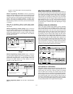
The front panel includes an autoranging (E3614A single-
range) digital voltmeter and a single-range digital ammeter.
Two 3 1/2 digit voltage and current displays accurately show
the output voltage and current respectively. The output rat-
ings for each model are shown in the Specifications and
Operating Characteristics Table.
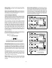
The OVP/CC SET switch is used to check the OVP trip volt-
age and current control set value. When pressing this switch,
the voltage display indicates the OVP trip voltage and the cur-
rent display indicates the current control set value.
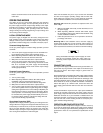
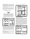
The power supply has both front and rear output terminals.
Either the positive or negative output terminal may be