


A-10
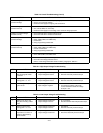
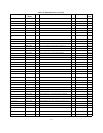
SYMPTOM CHECKS AND PROBABLE CAUSES
Poor Load Re
g
ulation
(Constant Volta
g
e)
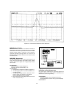
a. Refer to "Measurements Techniques" para
g
raph.
b. Check +10 V reference volta
g
e.
c. Ensure that the suppl
y
is not
g
oin
g
into current limit.
Poor Load Re
g
ulation
(Constant Current)
a. Check +10 V reference volta
g
e.
b. CR1, CR19, CR20, C2, C31 leak
y
.
c. Ensure that the suppl
y
is not crossin
g
over to constant volta
g
e operation.
Oscillates (Constant Volta
g
e/
Constant Current)
a. Check C29 and C36 in constant volta
g
e circuit.
b. Check C31 and C33 in constant current circuit.
Poor Stabilit
y
(Constant Volta
g
e)
a. Check +10 V reference volta
g
e.
b. CR27, CR28, CR23, and CR26 leak
y
.
c. U9 defective.
d. Nois
y
pro
g
rammin
g
resistor R83.
Poor Stabilit
y
(Constant Current)
a. Check +10 V reference volta
g
e.
b. CR24, CR25, CR29, and CR30 leak
y
.
c. U9 and U10 defective.
d. Nois
y
pro
g
rammin
g
resistor R85.
Excessive heat a. Check prere
g
ulator control circuit. Refer to Table A-6.
b. CR10, CR12, CR15, and CR18 short
OVP Shutdown a. Check that the front panel OVP Adjust screw control is rotated full
y
clockwise.
b. Check the overvolta
g
e protection circuit.
Refer to "Overvolta
g
e Protection Circuit Troubles" para
g
raph or Table A-7.
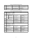
Table A-3. Overall Troubleshootin
g
(Cont’d)
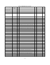
Table A-4. Hi
g
h Output Volta
g
e Troubleshootin
g
STEP ACTION RESPONSE PROBABLE CAUSE
1 Check turn off of Q1 and
Q4 b
y
shortin
g
Q9 emitter
to collector.
a. Output volta
g
e remains hi
g
h.
b. Output volta
g
e decreases.
a. Q1 or Q4 shorted.
b. Remove short and proceed to step 2.
2 Check turn on of Q9 b
y
shortin
g
point 1 to -12 V.
a. Output volta
g
e remains hi
g
h.
b. Output volta
g
e decreases.
a. Q9 open.
b. Remove short and proceed to step 3.
3 Check volta
g
e from pin 5
to pin 6 of U9.
a. Input volta
g
e is positive.
b. Input volta
g
e is ne
g
ative.
a. U9B is defective.
b. Turn down the volta
g
e control full
y
counter clockwise. Check the volta
g
e
of U9 pin 1 is 0.
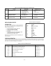
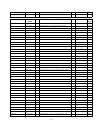
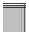
Table A-5. Low Output Volta
g
e Troubleshootin
g
STEP ACTION RESPONSE PROBABLE CAUSE
1 Check turn on of Q1 and
Q4 b
y
disconnectin
g
emitter
of Q9.
a. Output volta
g
e remains low.
b. Output volta
g
e increases.
a. Q1 or Q4 open.
b. Reconnect emitter lead and proceed to step 2.
2 Check turn off of Q9 b
y
shortin
g
point 1 to +15 V.
a. Output volta
g
e remains low.
b. Output volta
g
e increases.
a. Q9 shorted.
b. Remove short and proceed to step 3.
3 Eliminate constant current
comparator as a source of
trouble b
y
disconnectin
g
anode of CR22.
a. Output volta
g
e is increases.
b. Output volta
g
e remains low.
a. Proceed to step 4.
b. Reconnect lead and proceed to step 5.