


A-9
After the trouble has been isolated to one of the feedback
loops, troubleshootin
g
can proceed as described in Tables A-
4, A-5, or A-6.
Series Re
g
ulatin
g
Feedback Loop. When troubleshootin
g
the series re
g
ulatin
g
loop, it is useful to open the loop since
measurements made an
y
where within a closed loop ma
y
appear abnormal. With a loop closed, it is ver
y
difficult to sep-
arate cause from effect. As described in Tables A-4 and A-5,
the conduction or cutoff capabilit
y
of each sta
g
e is checked
b
y
shortin
g
or openin
g
a previous sta
g
e, as follows:
1. Shortin
g
the emitter to collector of a transistor simu-
lates saturation, or the full ON condition.
2. Shortin
g
the emitter to base of a transistor cuts it off,
and simulates an open circuit between emitter and
collector.
Althou
g
h a lo
g
ical first choice mi
g
ht be to break the loop
somewhere near its mid-point, and then perform successive
subdividin
g
tests, it is more useful to trace the loop from the
series re
g
ulator backwards a sta
g
e at a time, since loop fail-
ures occur more often at the hi
g
her power levels.
Prere
g
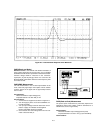
ulator Feedback Loop. The prere
g
ulator feedback
loop (SCR control circuit) can be convenientl
y
checked usin
g
Table A-6. As indicated in Table A-6, the control circuit is
checked b
y
startin
g
with the waveform at point 7 and point 6
(shown on the schematic dia
g
ram) and tracin
g
forwards and
backwards from this point.
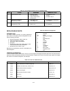
Overvolta
g
e Protection Circuit Troubles
When troubleshootin
g
the overvolta
g
e protection circuit, it is
useful to check the turn-on overshoot control circuit which
includes U20 and Q10. The function of the control circuit is to
slow down the risin
g
speed of the +15 V bias the moment the
power is turned on. This function prevents the suppl
y
from
false OVP trippin
g
the moment the power is turned on. After
the troubles has been isolated to overvolta
g
e protection cir-
cuit, troubleshootin
g
can proceed as described in Table A-7.
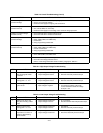
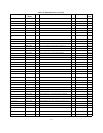
Table A-2. Reference and Bias Circuit Troubleshootin
g
METER
COMMON
METER
POSITIVE
NORMAL INDICATION NORMAL RIPPLE
(p-p)
PROBABLE CAUSE
TP6 point 2 +15.0 +/- 0.3 Vdc 2 mV Check U13, CR31, and CR32.
TP6 point 4 -12.0 +/- 0.3 Vdc 2 mV Check +15 V bias or U14.
TP6 TP7 +10.5 +/- 0.2 Vdc 2 mV Check +15 V bias, U11, and U14.
TP6 point 3 -5.1 +/- 0.5 Vdc 2 mV Check -12 V bias or VR1.
TP6 point 5 +5.0 +/- 0.3 Vdc 4 mV Check U1 and CR2.
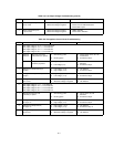
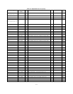
Table A-3. Overall Troubleshootin
g
SYMPTOM CHECKS AND PROBABLE CAUSES
Hi
g
h Output Volta
g
e a. Check series re
g
ulator feedback loop or prere
g
ulator feedback loop.
b. Refer to "Re
g
ulatin
g
Loop Troubles" para
g
raph or Table A-4 or A-6 as instructed.
Low and No Output Volta
g
e a. If output is zero, check fuse.
b. Check series re
g
ulator feedback loop or prere
g
ulator loop.
Refer to "Re
g
ulatin
g
Loop Troubles" para
g
raph or Table A-5 or A-6 as instructed.
c. Check CR20 shorted.
Hi
g
h Ripple a. Check operatin
g
setup for
g
round loops.
b. If output floatin
g
, connect 1 µF capacitor between output and
g
round.
c. Ensure that the suppl
y
is not crossin
g
over to constant current mode
under loaded conditions.
d. Check for low volta
g
e across C7 or Q1 and Q4.
e. Check for excessive ripple on reference volta
g
es (Table A-2).
Poor Line Re
g
ulation
(Constant Volta
g
e)
a. Check +10 V reference volta
g
e.
b. Check U9.