


A-11
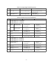
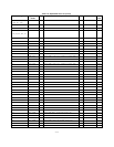
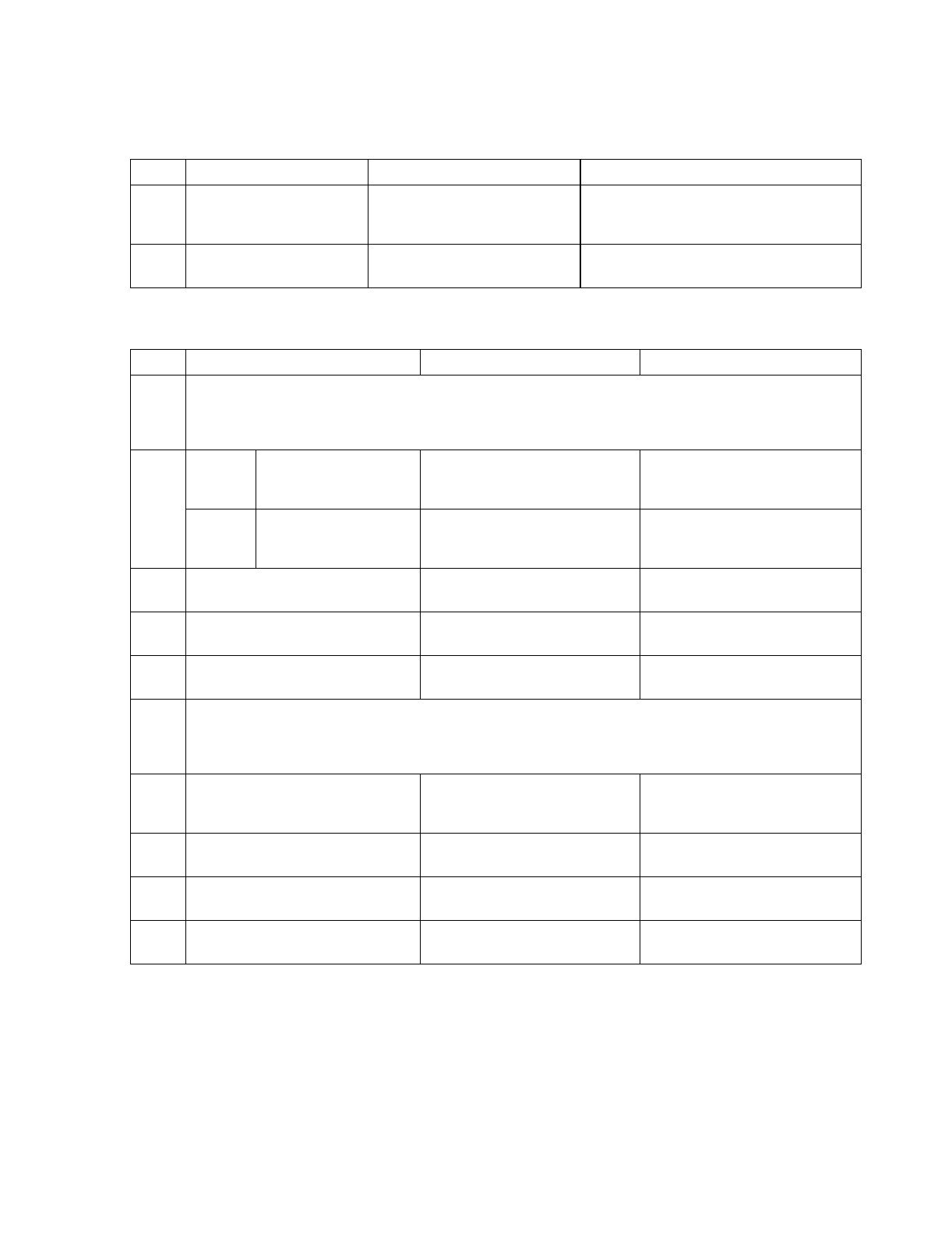
STEP ACTION RESPONSE PROBABLE CAUSE
4 Check volta
g
e from pin 13 to
pin 12 of U9.
a. Measured volta
g
e is positive.
b. Measured volta
g
e is ne
g
ative.
a. Check U9A is defective.
b. Check U10 and U9D is defective.
Check R85 is open.
5 Check volta
g
e from pin 6
to pin 5 of U9.
a. Measured volta
g
e is positive.
b. Measured volta
g
e is ne
g
ative.
a. U9B is defective.
b. Check U9C is defective.
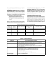
Table A-5. Low Output Volta
g
e Troubleshootin
g
(Cont’d)
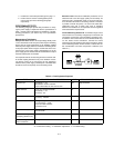
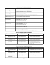
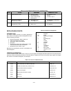
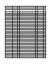
Table A-6. Prere
g
ulator/Control Circuit Troubleshootin
g
STEP MEASURE RESPONSE PROBABLE CAUSE
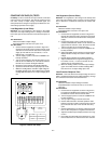
1 Set output volta
g
e to 4.5 V +- 0.5 V for E3614A.
Set output volta
g
e to 10 V +- 1 V for E3615A.
Set output volta
g
e to 15 V +- 1 V for E3616A.
Set output volta
g
e to 26 V +- 5 V for E3617A.
2 E3614A
E3615A
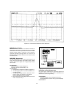
Waveform form from
TP6(common) to point 6
a. Normal firin
g
pulse
b. No firin
g
pulse
a. Check CR18, CR15, Q7, Q8
for defective.
b. Proceed to step 3.
E3616A Volta
g
e from TP6
(common) to point 6
a. Hi
g
h volta
g
e (+0.7 V)
b. Low volta
g
e (0 V)
a. CR15, CR18, U2, U21
defective
b. Proceed to step 3.
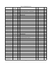
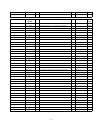
3 Volta
g
e from TP6(common) to
U4 pin 1
a. Low volta
g
e (-12 V)
b. Hi
g
h volta
g
e (+5 V)
a. U3 defective
b. Proceed to step 4.
4 Volta
g
e from TP6(common) to
U5 pin 1
a. Hi
g
h volta
g
e (+15 V)
b. Low volta
g
e (-12 V)
a. U4 defective
b. Proceed to step 5.
5 Volta
g
e from pin 6 to
pin 7 of U5
a. Measured volta
g
e is positive.
b. Measured volta
g
e is ne
g
ative.
a. U5 defective
b. U6 defective
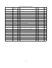
6 Set output volta
g
e to 7 V +- 1 V for E3614A.
Set output volta
g
e to 16 V +- 2 V for E3615A.
Set output volta
g
e to 25 V +- 2 V for E3616A.
Set output volta
g
e to 44 V +- 5 V for E3617A.
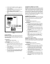
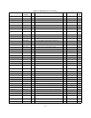
7 Waveform form from TP6
(common) to point 7
a. Normal firin
g
pulse
b. No firin
g
pulse
a. CR10, CR12, Q5, Q6
defective
b. Proceed to step 8.
8 Volta
g
e from TP6(common)
to U4 pin 14
a. Low volta
g
e (-12 V)
b. Hi
g
h volta
g
e (+5 V)
a. U3 defective
b. Proceed to step 9.
9 Volta
g
e from TP6(common)
to U5 pin 14
a. Hi
g
h volta
g
e (+15 V)
b. Low volta
g
e (-12 V)
a. U4 defective
b. Proceed to step 10.
10 Volta
g
e from pin 8 to
pin 9 of U5
a. Measured volta
g
e is positive.
b. Measured volta
g
e is ne
g
ative.
a. U5 defective
b. U6 defective