


1-10
pl
y
above 100% rated output. Limit
y
our pro
g
rammin
g
volta
g
e to 10 Vdc.
Remote Pro
g
rammin
g
Connections. Remote pro
g
rammin
g
requires chan
g
in
g
settin
g
s of the switch and connectin
g
external
volta
g
es to + and - terminals of "CV" or "CC" on the rear panel.
An
y
noise picked up on the pro
g
rammin
g
leads will appear on the
suppl
y
's output and ma
y
de
g
rade re
g
ulation. To reduce noise
pick-up, use a twisted or shielded pair of wires for pro
g
rammin
g
,
with the shield
g
rounded at one end onl
y
. Do not use the shield as
a conductor.
Notice that it is possible to operate a power suppl
y
simulta-
neousl
y
in the remote sensin
g
and the remote analo
g
pro
g
ram-
min
g
modes.
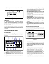
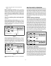
Remote Pro
g
rammin
g
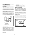
, Constant Volta
g
e. Fi
g
ure 6 shows the
rear panel switch settin
g
s and terminal connections for remote-
volta
g
e control of output volta
g
e. A 1 Vdc chan
g
e in the remote
pro
g
rammin
g
volta
g
e produces a chan
g
e in output volta
g
e (volt-
a
g
e
g
ain) as follows: E3614A: 0.8 Vdc, E3615A: 2 Vdc, E3616A:
3.5 Vdc, E3617A: 6 Vdc
Fi
g
ure 6. Remote Volta
g
e Pro
g
rammin
g
, Constant
Volta
g
e
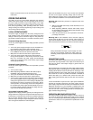
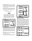
Remote Pro
g
rammin
g
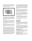
, Constant Current. Fi
g
ure 7 shows the
rear panel switch settin
g
s and terminal connections for remote-
volta
g
e control of output current. A 1 Vdc chan
g
e in the remote
pro
g
rammin
g
volta
g
e produces a chan
g
e in output current (cur-
rent
g
ain) as follows: E3614A: 0.6 Adc, E3615A: 0.3 Adc,
E3616A: 0.17 Adc, E3617A: 0.1 Adc
Fi
g
ure 7. Remote Volta
g
e Pro
g
rammin
g
, Constant
Current
Remote Pro
g
rammin
g
Speed. See the table of Specifications,
pa
g
e 1-5.
MULTIPLE-SUPPLY OPERATION
Normal parallel and auto-parallel operation provides increased out-
put current while normal series and auto-series provides increased
output volta
g
e. Auto-trackin
g
provides sin
g
le control of output volt-
a
g
e of more than one suppl
y
. You can set up the unit for multiple-
suppl
y
operation b
y
chan
g
in
g
the settin
g
s of the rear panel switch
and connectin
g
the leads from the rear panel terminals to the load.
Solid conductors of 0.75 to 1.5 mm
2
can be connected to the rear
panel terminals b
y
simpl
y
push fittin
g
. Thinner wires or conductors
are inserted into the connection space after depressin
g
the oran
g
e
openin
g
lever.
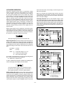
NORMAL PARALLEL OPERATION
Two or more power supplies bein
g
capable of CV/CC automatic
cross over operation can be connected in parallel to obtain a total
output current
g
reater than that available from one power suppl
y
.
The total output current is the sum of the output currents of the
individual power supplies. The output of each power suppl
y
can
be set separatel
y
. The output volta
g
e controls of one power sup-
pl
y
should be set to the desired output volta
g
e; the other power
suppl
y
should be set for a sli
g
htl
y
hi
g
her output volta
g
e. The sup-
pl
y
with the hi
g
her output volta
g
e settin
g
will deliver its constant
current output, and drop its output volta
g
e until it equals the out-
put of the other suppl
y
, and the other suppl
y
will remain in con-
stant volta
g
e operation and onl
y
deliver that fraction of its rated
output current which is necessar
y
to fulfill the total load demand.
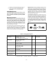
Fi
g
ure 8 shows the rear panel switch settin
g
s and terminal con-
nections for normal parallel operation of two supplies.
Fi
g
ure 8. Normal Parallel Operation of Two Supplies
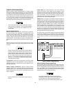
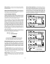
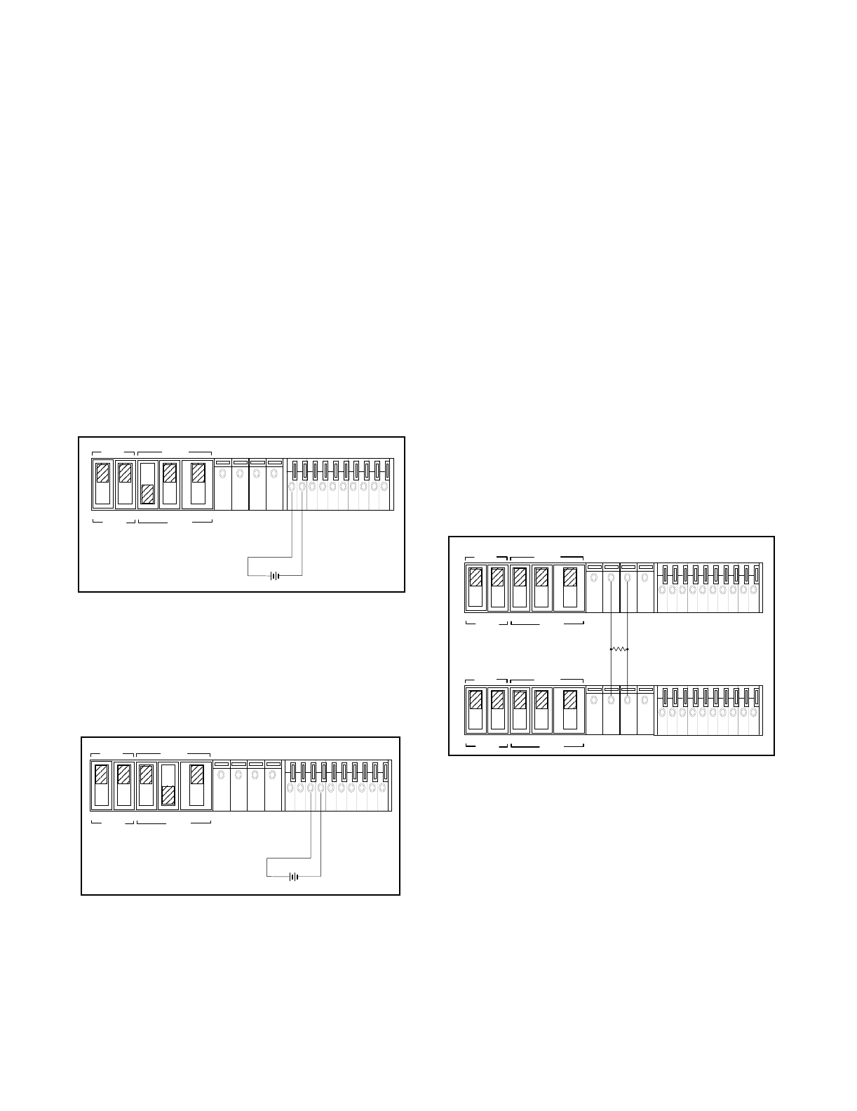
AUTO-PARALLEL OPERATION
Auto-parallel operation permits equal current sharin
g
under all load
conditions, and allows complete control of output current from one
master suppl
y
. The control unit is called the master; the controlled
units are called slaves. Normall
y
, onl
y
supplies havin
g
the same
model number should be connected for auto-parallel operation,
since the supplies must have the same volta
g
e drop across the cur-
rent monitorin
g
resistor at full current ratin
g
. The output current of
each slave is approximatel
y
equal to the master's. Fi
g
ure 9 and Fi
g
-
ure 10 show the rear panel switch settin
g
s and terminal connections
for auto-parallel operation of two supplies and three supplies.
MASTER
SLAVE
CV CC SENSE
LOCAL
REMOTE
OUT
+S
-S
+
_
CV CC
VREF
A1 A2 A3 A4 A5
+
+
M/S 1 M/S 2
_
_
NOTE:
See the supplementar
y
Manual, if
y
ou are not usin
g
isolated pro
g
rammin
g
volta
g
e source.
MASTER
SLAVE
CV CC SENSE
LOCAL
REMOTE
OUT
+S
-S
+
_
CV CC
VREF
A1 A2 A3 A4 A5
+
+
M/S 1 M/S 2
_
_
NOTE:
See the supplementar
y
Manual, if
y
ou are not usin
g
isolated pro
g
rammin
g
volta
g
e source.
MASTER
SLAVE
CV CC SENSE
LOCAL
REMOTE
OUT
+S -S
+
_
CV CC
VREF
A1 A2 A3 A4 A5
+
+
M/S 1 M/S 2
__
MASTER
SLAVE
CV CC SENSE
LOCAL
REMOTE
OUT
+S
-S
+
_
CV CC
VREF
A1 A2 A3 A4 A5
+
+
M/S 1 M/S 2
_
_
POWER SUPPLY
POWER SUPPLY
LOAD