


A-6
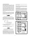
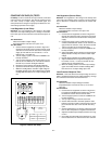
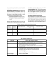
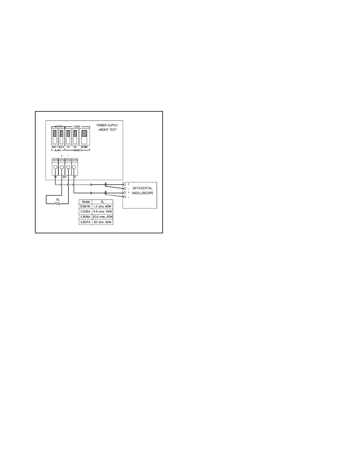
a. Connect the test equipment as shown in Fi
g
ure A-7.
b. Turn the suppl
y
's power on and turn CURRENT con-
trol full
y
clockwise.
c. Turn up output volta
g
e to the full rated value. Check
that the suppl
y
's CV indicator remains li
g
hted.
Reduce VOLTAGE control if not li
g
hted.
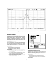
d. Set the oscilloscope to AC mode and bandwidth to 20
MHz.
e. Check that the peak-to-peak noise is less than 1 mV.
Fi
g
ure A-7.
B
CV PARD Peak-to-Peak Measurement Test
Setup
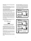
CV Drift (Stability)
Definition: The chan
g
e in output volta
g
e (dc to 20 Hz) for the
first 8 hours followin
g
a 30-minute warm-up period with con-
stant input line volta
g
e, constant load resistance and constant
ambient temperature.
Test Parameter:
Measured Variable: Output Volta
g
e
Expected Results: Less than 0.1% plus 5 mV
Test Procedure:
a. Connect the DVM across Rs in Fi
g
ure A-4.
b. Operate the electronic load in constant current mode
and set its current to the full rated value of power sup-
pl
y
.
c. Turn the suppl
y
's power on and turn CURRENT con-
trol full
y
clockwise.
d. Turn up output volta
g
e to the full rated value as read
on the di
g
ital voltmeter.
e. After a 30-minute warm-up, note the volta
g
e on DVM.
f. The output volta
g
e readin
g
should deviate less than
0.1% plus 5 mV from the readin
g
obtained in step e
over a period of 8 hours.
CONSTANT CURRENT (CC) TESTS
CC Setup. Constant current tests are analo
g
ous to constant
volta
g
e tests, with the suppl
y
's output short circuited and the
volta
g
e set to full output to assure CC operation. For output
current measurements the current monitorin
g
resistor must
be treated as a four terminal device. Refer to the "Measure-
ment Techniques" for details. All constant current measure-
ments are made in terms of the chan
g
e in volta
g
e across this
resistor; the current performance is calculated b
y
dividin
g
these volta
g
e chan
g
es b
y
ohmic value of Rs.
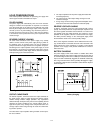
Load Re
g
ulation (Load Effect)
Definition: CC Load re
g
ulation is the chan
g
e in the stead
y
state
value of dc output current due to a chan
g
e in load resistance
from short circuit to full load or from full load to short circuit.
Test Parameter:
Measured Variable: Output Current
Expected Results: Less than 0.01% plus 250 µA
Test Procedure:
a. Connect the DVM across Rs in Fi
g
ure A-4. Operate
the electronic load in constant volta
g
e mode and set
its volta
g
e to the full rated value of power suppl
y
.
b. Turn the suppl
y
's power on and turn VOLTAGE con-
trol full
y
clockwise.
c. Turn up output current to the full rated value. Check
that the AMPS displa
y
reads full rated values and CC
indicator remains li
g
hted. Reduce CURRENT control
if not li
g
hted.
d. Record the volta
g
e across Rs and convert it to cur-
rent b
y
dividin
g
this volta
g
e b
y
Rs.
e. Operate the electronic load in short (input short)
mode.
f. When the readin
g
settles, record volta
g
e across Rs
a
g
ain and convert it current. Check that the two
recorded readin
g
s differ less than 0.01% of output
current plus 250 µA.
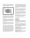
Line Re
g
ulation (Source Effect)
Definition:
Line re
g
ulation is the chan
g
e in the stead
y
state
value of dc output current due to a chan
g
e in ac input volta
g
e
from the minimum to maximum value(±10% of nominal volta
g
e).
Test Parameter:
Measured Variable: Output Current
Expected Results: Less than 0.01% plus 250 µA
Test Procedure:
a. Connect the DVM across Rs in Fi
g
ure A-4. Operate
the electronic load in constant volta
g
e mode and set
its volta
g
e to the full rated value of power suppl
y
.
b. Connect the suppl
y
to the ac power line throu
g
h a
variable autotransformer that set for low line volt-
a
g
e(104 Vac for nominal 115 Vac, 90 Vac for nominal
100 Vac, and 207 Vac for nominal 230 Vac).
c. Turn the suppl
y
's power on and turn VOLTAGE con-
trol full
y
clockwise.
d. Turn up output current to the full rated value. Check
that the AMPS displa
y
reads full rated values and CC
indicator remains li
g
hted. Reduce CURRENT control
if not li
g
hted.