


1-14
LOAD CONSIDERATIONS
This section provides information on operatin
g
y
our suppl
y
with
various t
y
pes of loads connected to its output.
PULSE LOADING
The power suppl
y
will automaticall
y
cross over from constant-
volta
g
e to constant current operation in response to an increase
(over the preset limit) in the output current. Althou
g
h the preset
limit ma
y
be set hi
g
her than the avera
g
e output current, hi
g
h peak
currents (as occur in pulse loadin
g
) ma
y
exceed the preset cur-
rent limit and cause cross over to occur. If this cross over limitin
g
is not desired, set the preset limit for the peak requirement and
not the avera
g
e.
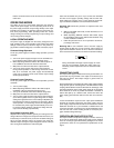
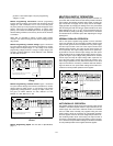
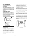
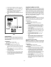
REVERSE CURRENT LOADING
An active load connected to the power suppl
y
ma
y
actuall
y
deliver a reverse current to the power suppl
y
durin
g
a portion of
its operatin
g
c
y
cle. An external source can not be allowed to
pump current into the suppl
y
without loss of re
g
ulation and possi-
ble dama
g
e to the output capacitor of the power suppl
y
. To avoid
these effects, it is necessar
y
to preload the suppl
y
with a dumm
y
load resistor so that the power suppl
y
delivers current throu
g
h the
entire operatin
g
c
y
cle of the load devices.
Fi
g
ure 16. Reverse Current Loadin
g
Solution
OUTPUT CAPACITANCE
An internal capacitor, connected across the output terminals of
the power suppl
y
, helps to suppl
y
hi
g
h-current pulses of short
duration durin
g
constant volta
g
e operation. An
y
capacitance
added externall
y
will improve the pulse current capabilit
y
, but will
decrease the safet
y
provided b
y
the current limitin
g
circuit. A
hi
g
h-current pulse ma
y
dama
g
e load components before the
avera
g
e output current is lar
g
e enou
g
h to cause the current limit-
in
g
circuit to operate.
The effect of the output capacitor durin
g
constant current opera-
tion are as follows:
a. The output impedance of the power suppl
y
decreases with
increasin
g
frequenc
y
.
b. The recover
y
time of the output volta
g
e is lon
g
er for load
resistance chan
g
es.
c. A lar
g
e sur
g
e current causin
g
a hi
g
h power dissipation in the
load occurs when the load resistance is reduced rapidl
y
.
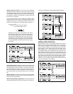
REVERSE VOLTAGE LOADING
A diode is connected across the output terminals with reverse
polarit
y
. This diode protects the output electrol
y
tic capacitors and
the series re
g
ulator transistors from the effects of a reverse volt-
a
g
e applied across the output terminals. For example, in series
operation of two supplies, if the AC is removed from one suppl
y
,
the diode prevents dama
g
e to the unener
g
ized suppl
y
which
would otherwise result from a reverse polarit
y
volta
g
e.
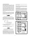
Since series re
g
ulator transistors cannot withstand reverse volt-
a
g
e, another diode is connected across the series transistor. This
diode protects the series re
g
ulators in parallel or auto-parallel
operation if one suppl
y
of the parallel combination is turned on
before the other.
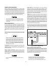
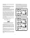
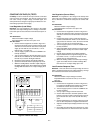
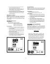
BATTERY CHARGING
The power suppl
y
's OVP circuit contains a crowbar SCR, which
effectivel
y
shorts the output of the suppl
y
whenever the OVP trips. If
an external volta
g
e source such as a batter
y
is connected across the
output, and OVP inadvertentl
y
tri
gg
ered, the SCR will continuousl
y
sink a lar
g
e current from the source; possibl
y
dama
g
in
g
the suppl
y
.
To avoid this a diode must be connected in series with the output as
shown in Fi
g
ure 17.
Fi
g
ure 17. Recommended Protection Circuit for
Batter
y
Char
g
in
g