


1-6
Table 1. Specifications and Operating Characteristics (Cont’d)
*REMOTE PROGRAMMING SPEED
Maximum time required for output voltage to change from initial
value to within a tolerance band (0.1%) of the newly programmed
value following the onset of a step change in the programming
input voltage.
Full load No load
Up: E3614A:
3 msec 2 msec
E3615A:
9 msec 6 msec
E3616A:
85 msec 85 msec
E3617A:
200 msec 200 msec
Down:
E3614A:
7 msec 1.6 sec
E3615A:
13 msec 2.2 sec
E3616A:
65 msec 1.8 sec
E3617A:
200 msec 3.2 sec
DC ISOLATION
± 240 Vdc maximum between either output terminal and earth
ground including the output voltage.
*COOLING:
Convection cooling is employed.
*WEIGHT:
12.1 lbs/5.5 Kg net, 14.9 lbs/6.75 Kg shipping.
* Operating Characteristics
INSTALLATION
INITIAL INSPECTION
Before shipment, this instrument was inspected and found to be
free of mechanical and electrical defects. As soon as the instru-
ment is unpacked, inspect for any damage that may have
occurred in transit. Save all packing materials until the inspection
is completed. If damage is found, a claim should be filed with the
carrier. The Agilent Technologies Sales and Service office should
be notified.
Mechanical Check
This check should confirm that there are no broken knobs or connec-
tors, that the cabinet and panel surfaces are free of dents and
scratches, and that the meter is not scratched or cracked.
Electrical Check
The instrument should be checked against its electrical specifi-
cations. Paragraph "TURN-ON CHECKOUT PROCEDURE" con-
tains a brief checkout procedure and "PERFORMANCE TEST" in
section SERVICE INFORMATION includes an instrument perfor-
mance check to verify proper instrument operation.
INSTALLATION DATA
The instrument is shipped ready for bench operation. It is neces-
sary only to connect the instrument to a source of power and it is
ready for operation.
Location and Cooling
This instrument is air cooled. Sufficient space should be allowed so
that a free flow of cooling air can reach the sides and rear of the
instrument when it is in operation. It should be used in an area where
the ambient temperature does not exceed 40
o
C. Maximum current is
derated 1% per
o
C at 40
o
C-55
o
C.
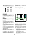
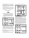
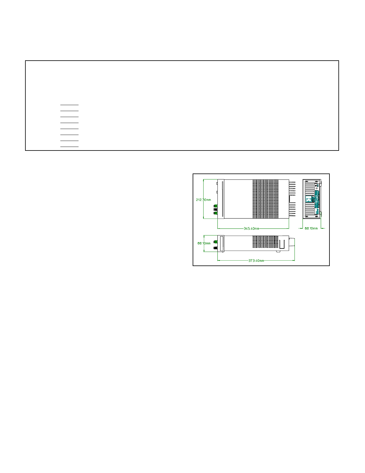
Outline Diagram
Figure 1 is a outline diagram showing the dimensions of the
instrument.
Rack Mounting
This instrument may be rack mounted in a standard 19-inch rack
panel either by itself or alongside a similar unit. Please see
ACCESSORY, page 1-4, for available rack mounting accesso-
ries. Each rack-mounting kit includes complete installation
instructions.
Figure 1. Outline Diagram
INPUT POWER REQUIREMENTS
This power supply may be operated from nominal 100, 115, or
230 Vac 47-63 Hertz power source. A label on the rear panel
shows the nominal input voltage set for the unit at the factory. If
necessary, you can convert the supply to another nominal input
voltage by following the instructions below
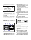
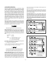
Line Voltage Option Conversion
Line voltage conversion is accomplished by adjusting two compo-
nents: the line select switch and the rear panel fuse F1. To con-
vert the supply from one line voltage option to another, proceed
as follows:
a.Disconnect power cord.
b.Turn off the supply and remove the top cover by lifting the
cover upwards after taking it off from both sides of the chassis
by inserting a flat-blade screwdriver into the gap on the lower
rear portion of the cover.
c.Set two sections of the line voltage selector switch on the PC
board for the desired line voltage (see Figure 2).
d.Check the rating of the fuse F1 installed in the rear panel fuse
holder and replace with the correct fuse if necessary. For 100
and 115 V operation, use a normal blow 2 A fuse and for 230
V use a time delay 1 A fuse.