


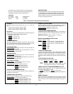


1-8
that the current limit value can be set from zero to maximum
rated value.
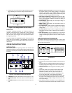
OPERATING MODES
The settin
g
of the rear panel switch determines the operatin
g
modes of the power suppl
y
. The local operatin
g
mode is set so
the power suppl
y
senses the output volta
g
e directl
y
at the output
terminals (local sensin
g
) for operation usin
g
the front panel con-
trols (local pro
g
rammin
g
). Other operatin
g
modes are: remote
volta
g
e sensin
g
and remote pro
g
rammin
g
of output volta
g
e and
current usin
g
external volta
g
es.
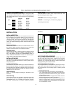
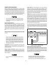
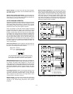
LOCAL OPERATING MODE
The power suppl
y
is shipped from the factor
y
confi
g
ured in the
local operatin
g
mode. Local operatin
g
mode requires the switch
settin
g
s of the rear panel, as shown in Fi
g
ure 4. The power sup-
pl
y
provides constant volta
g
e(CV) or constant current(CC) output.
Constant Volta
g
e Operaton
To set up a power suppl
y
for constant volta
g
e operation, proceed
as follows:
a. Turn on the power suppl
y
and adjust 10-turn VOLTAGE con-
trol for desired output volta
g
e (output terminals open).
b. While depressin
g
DISPLAY OVP/CC SET switch, adjust 10-
turn CURRENT control for the desired current limit.
c. With power off connect the load to the output terminals.
d. Turn on the power suppl
y
. Verif
y
that CV LED is li
g
hted.
Durin
g
actual operation, if a load chan
g
e causes the current
limit to be exceeded, the power suppl
y
will automaticall
y
cross over to constant current mode and the output volta
g
e
will drop proportionatel
y
.
Constant Current Operation
To set up a power suppl
y
for constant current operation, proceed
as follows:
a. Turn on power suppl
y
.
b. While depressin
g
DISPLAY OVP/CC SET switch, adjust
CURRENT control for the desired output current.
c. Turn up the VOLTAGE control to the desired volta
g
e limit.
d. With power off connect the load to the output terminal.
e. Turn on power suppl
y
and then verif
y
that CC LED is li
g
hted.
(If CV LED is li
g
hted, choose a hi
g
her volta
g
e limit. A volta
g
e
settin
g
that is
g
reater than the current settin
g
multiplied b
y
the
load resistance in ohms is required for CC operation.) Durin
g
actual operation, if a load chan
g
e causes the volta
g
e limit to
be exceeded, the power suppl
y
will automaticall
y
cross over
to constant volta
g
e operation at the preset volta
g
e limit and
output current will drop proportionatel
y
.
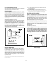
Overvolta
g
e Protection (OVP)
Adjustable overvolta
g
e protection
g
uards
y
our load a
g
ainst over-
volta
g
e. When the volta
g
e at the output terminals increases (or is
increased b
y
an external source) to the OVP shutdown volta
g
e as
set b
y
the OVP ADJUST control, the suppl
y
's OVP circuit dis-
ables the output causin
g
the output volta
g
e and current to drop to
zero. Durin
g
OVP shutdown the OVP LED li
g
hts.
False OVP shutdowns ma
y
occur if
y
ou set the OVP shutdown
too close to the suppl
y
's operatin
g
volta
g
e. Set the OVP shut-
down volta
g
e 4% of output +2.0 V or more above the output volt-
a
g
e to avoid false shutdowns from load-induced transients.
Ad
j
ustin
g
OVP.
Follow this procedure to adjust the OVP shut-
down volta
g
e.
a. With the VOLTAGE control full
y
counter clockwise, turn on
the power suppl
y
.
b. While depressin
g
DISPLAY OVP/CC SET switch, adjust
the OVP Adjust control to the desired OVP shutdown usin
g
a small, flat-blade screwdriver.
c. Follow the procedure for CC or CV operaton to set the out-
put volta
g
e and current
Resettin
g
OVP. If OVP shutdown occurs, reset the suppl
y
b
y
turnin
g
power off. Wait one or more seconds, and turn power on
a
g
ain. If OVP shutdown continue to occur, check the connections
to the load and sense terminals, and check the OVP limit settin
g
..
Stron
g
electrostatic dischar
g
e to power suppl
y
can make
OVP trip and eventuall
y
crowbar the output, which can
effectivel
y
protect output loads from the hazardous ESD
current.
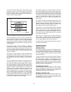
CONNECTING LOADS
The output of the suppl
y
is isolated from earth
g
round. Either out-
put terminal ma
y
be
g
rounded or the output can be floated up to
240 volts off
g
round. Total output volta
g
e to
g
round must not
exceed 240 Vdc.
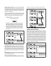
Each load should be connected to the power suppl
y
output terminals
usin
g
separate pairs of connectin
g
wires. This will minimize mutual
couplin
g
effects between loads and will retain full advanta
g
e of the
low output impedance of the power suppl
y
. Each pair of connectin
g
wires should be as short as possible and twisted or shielded to
reduce noise pick-up. (If a shield is used, connect one end to the
power suppl
y
g
round terminal and leave the other end unconnec-
ted.)
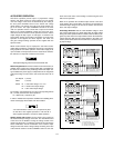
If load considerations require that the output power distribution
terminals be remotel
y
located from the power suppl
y
, then the
power suppl
y
output terminals should be connected to the remote
distribution terminals via a pair of twisted or shielded wires and
each load separatel
y
connected to the remote distribution termi-
nals. For this case, remote sensin
g
should be used (See para-
g
raph "Remote Volta
g
e Sensin
g
").
OPERATION BEYOND RATED OUTPUT
The output controls can adjust the volta
g
e or current to values up
to 5% over the rated output. Althou
g
h the suppl
y
can be operated
in the 5% overran
g
e re
g
ion without bein
g
dama
g
ed, it can not be
g
uaranteed to meet all of its performance specifications in this
re
g
ion.