


A-4
CONSTANT VOLTAGE (CV) TESTS
CV Setup.
For all CV tests set the output current at full rated
output to assure CV operation. The onset of constant current
can cause a drop in output volta
g
e, increased ripple, and
other performance chan
g
es not properl
y
ascribed to the con-
stant volta
g
e operation of the suppl
y
.
Load Regulation (Load Effect)
Definition:
CV Load re
g
ulation is the chan
g
e in the stead
y
state value of dc output volta
g
e due to a chan
g
e in load resis-
tance from open circuit to full load or from full load to open cir-
cuit.
Test Parameters:
Measured Variable: Output Volta
g
e
Expected Results: Less than 0.01% plus 2 mV
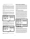
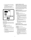
Test Procedure:
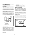
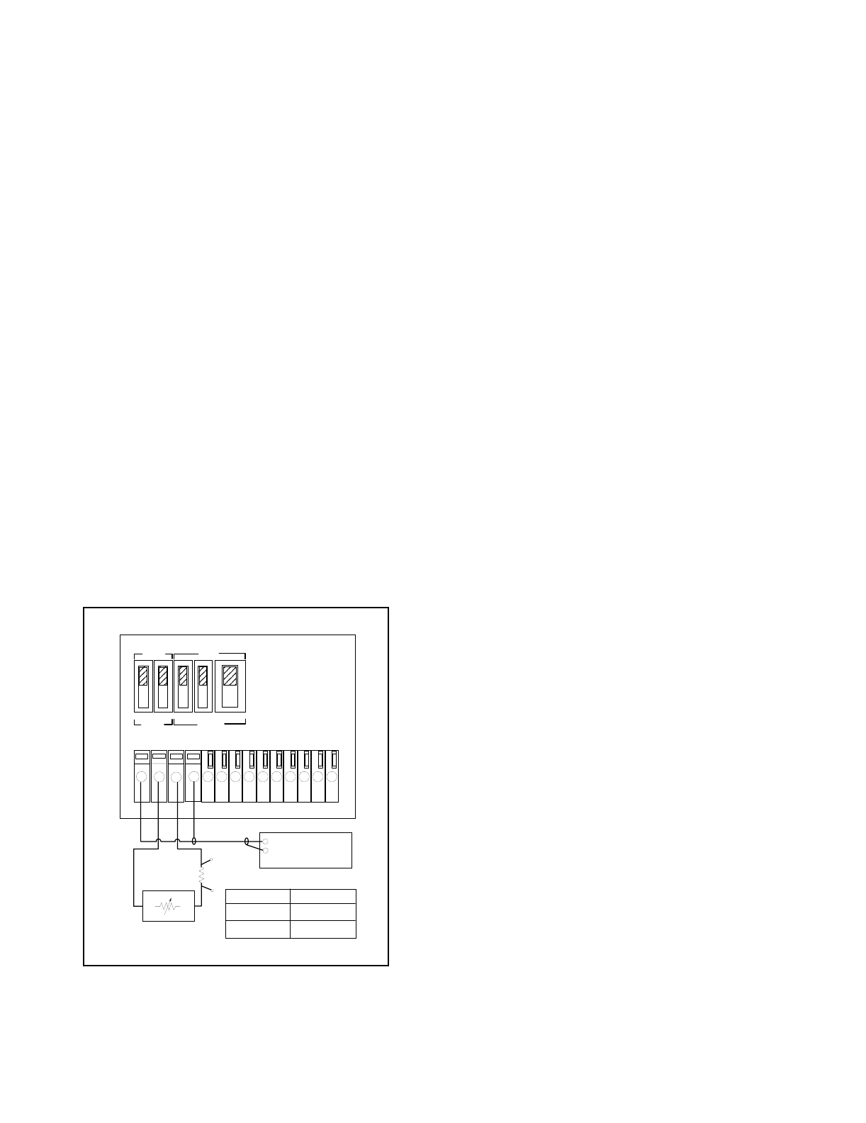
a. Connect the test equipment as shown in Fi
g
ure A-4.
Operate the electronic load in constant current mode
and set its current to the full rated value of the power
suppl
y
(6 A for E3614A, 3 A for E3615A, 1.7 A for
E3616A and 1 A for E3617A).
b. Turn the suppl
y
's power on and turn CURRENT con-
trol full
y
clockwise.
c. Turn up output volta
g
e to the full rated value (8 V for
E3614A, 20 V for E3615A, 35 V for E3616A and 60 V
for E3617A) as read on the di
g
ital voltmeter.
d. Record the output volta
g
e at the di
g
ital voltmeter.
e. Operate the electronic load in open(input off) mode.
f. When the readin
g
settles, record the output volta
g
e on
the di
g
ital voltmeter a
g
ain. Check that the two recorded
readin
g
s differ less than 0.01% of output volta
g
e plus 2
mV.
Fi
g
ure A-4. Basic Test Setup
Line Regulation (Source Effect)
Definition:
Line re
g
ulation is the chan
g
e in the stead
y
state
value of dc output volta
g
e due to a chan
g
e in ac input volta
g
e
from a minimum to a maximum value(±10% of nominal volt-
a
g
e).
Test Parameter:
Measured Variable: Output Volta
g
e
Expected Results: Less than 0.01% plus 2 mV
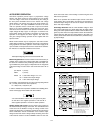
Test Procedure:
a. Connect the test equipment as shown in Fi
g
ure A-4.
Operate the electronic load in constant current mode
and set its current to the full rated value of the power
suppl
y
.
b. Connect the suppl
y
to the ac power line throu
g
h a
variable autotransformer which is set for low line volt-
a
g
e(104 Vac for nominal 115 Vac, 90 Vac for nominal
100 Vac, and 207 Vac for nominal 230 Vac).
c. Turn the suppl
y
's power on and turn CURRENT con-
trol full
y
clockwise.
d. Adjust VOLTAGE control until the front panel VOLTS
displa
y
indicates exactl
y
the maximum rated output
volta
g
e.
e. Record volta
g
e indicated on the di
g
ital voltmeter.
f. Adjust autotransformer to hi
g
h line volta
g
e(127 Vac
for nominal 115 Vac, 110 Vac for nominal 100 Vac,
and 253 Vac for nominal 230 Vac).
g
. When the readin
g
settles, record the output volta
g
e
a
g
ain. Check that the two recorded readin
g
s differ
less than 0.01% of output volta
g
e plus 2 mV.
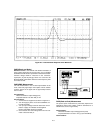
Load Transient Response Time
Definition :
This is the time for the output volta
g
e to return to
within a specified band around its volta
g
e followin
g
a chan
g
e
from full load to half load or half load to full load.
Test Parameter:
Measured Variable: Output Volta
g
e Transients
Expected Results: Less than 50 usec (at 15 mV from
base line)
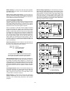
Test Procedure:
a. Connect the test equipment as shown in Fi
g
ure A-4,
but replace the DVM with the oscilloscope. Operate
the electronic load in constant current mode.
b. Turn the suppl
y
's power on and turn CURRENT con-
trol full
y
clockwise.
c. Turn up output volta
g
e to the full rated value.
d. Set the electronic load to transient operation mode
between one half of suppl
y
's full rated value and sup-
pl
y
's full rated value at a 1 KHz rate with 50% dut
y
c
y
cle.
e. Set the oscilloscope for ac couplin
g
, internal s
y
nc and
lock on either the positive or ne
g
ative load transient.
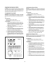
f. Adjust the oscilloscope to displa
y
transients as in Fi
g
-
ure A-5.
g
. Check that the pulse width of the transients at 15 mV
from the base line is no more than 50 usec as shown.
+-
+S
OUT
-S
+- +-
CV
+-
CC
A1 A2 A3 A4 A5VREF
ELECTRONIC
LOAD
+
-
DIGITAL
VOLTMETER
Rs
-
+
TO
DVM
POWER SUPPLY
UNDER TEST
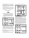
MASTER
LOCAL
SLAVE
REMOTE
Model
Rs
E3614A, 15A, 16A
E3617A
0.1 ohm 0.1% 10W
1 ohm 1% 5W
M/S 1 M/S 2
CV CC
SENSE