


1-13
Remote Sensin
g
. To remote sense with auto-series operation,
set SENSE switch of the master unit and set SENSE switch of the
slave unit to remote.
Remote Analo
g
Volta
g
e Pro
g
rammin
g
. To remote analo
g
pro-
g
ram with auto-series operation, connect pro
g
ram (external) volt-
a
g
es to the "CV" or "CC"" terminal of the master unit and set "CV"
or "CC" switch of the master unit to remote.
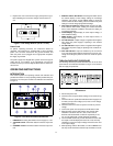
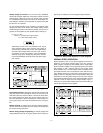
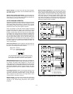
AUTO-TRACKING OPERATON
Auto-trackin
g
operation of power supplies is similar to auto-series
operation except that the master and slave supplies have the
same output polarit
y
with respect to a common bus or
g
round.
This operation is useful where simultaneous turn-up, turn-down or
proportional control of all power supplies is required.
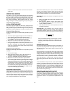
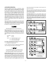
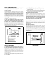
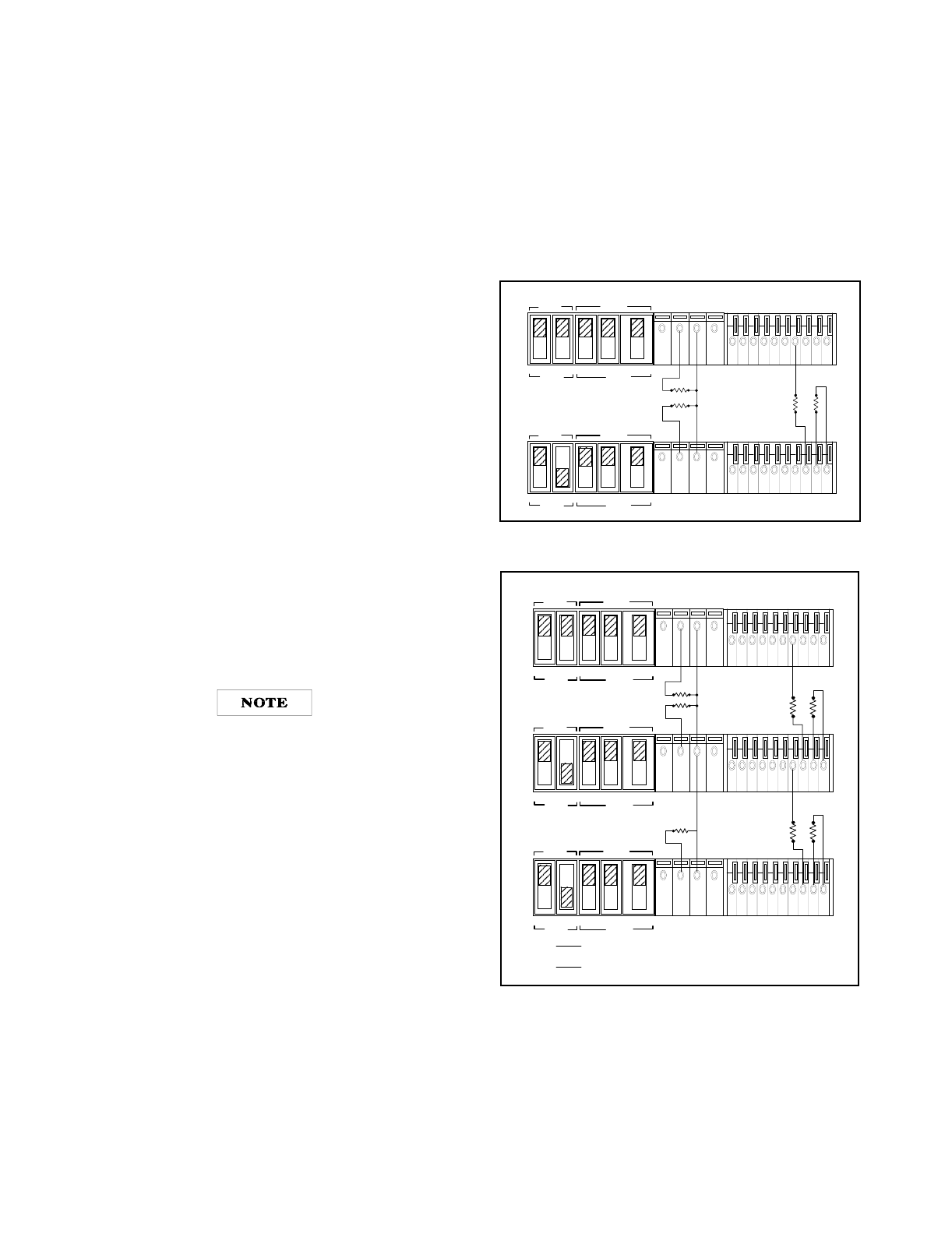
Fi
g
ure 14 and Fi
g
ure 15 show two and three supplies connected
in auto-trackin
g
with their ne
g
ative output terminals connected
to
g
ether as a common or
g
round point. For two units in auto-
trackin
g
a fraction R2/(R1+R2) of the output of the master suppl
y
is provided as one of the inputs to the comparison amplifier of the
slave suppl
y
, thus controllin
g
the slave's output. The master sup-
pl
y
in an auto-trackin
g
operation must be the positive suppl
y
hav-
in
g
the lar
g
est output volta
g
e. Turn-up and turn-down of the
power supplies are controlled b
y
the master suppl
y
. In order to
maintain the temperature coefficient and stabilit
y
specifications of
the power suppl
y
, the external resistor should be stable, low
noise, low temperature.
Determinin
g
Resistors. External resistors control the fraction of
the master unit's volta
g
e that is supplied from the slave unit. For
two units in auto-trackin
g
the ratio R1 and R2 is
R2/(R1+R2 = (Vs/Vm)
Where Vm = master output volta
g
e
Vs = slave output volta
g
e
It is recommended to connect a 0.1 µF capacitor in paral-
lel with R2 in two supplies operation or R2 and R4 in
three supplies operation to ensure the stable operation.
Settin
g
Volta
g
e and Current. Use the master unit's VOLTAGE con-
trol to set the output volta
g
e from both units. When the master is in
CV operation, the master's output volta
g
e(Vm) is the same as its
volta
g
e settin
g
, and the slave's output volta
g
e for two units operation
is Vm(R2/(R1+R2)). The VOLTAGE control of the slave unit is dis-
abled. Set the CURRENT controls of master and slave units above
the required currents to assure CV operation of master and slave
units.
Overvolta
g
e Protection. Set the OVP shutdown volta
g
e in each
unit so that it shuts down at a volta
g
e hi
g
her than its output volt-
a
g
e durin
g
auto-trackin
g
operation. When a master unit shuts
down, it pro
g
rams an
y
slave units to zero output. When a slave
unit shuts down, it shuts down onl
y
itself.
Remote Sensin
g
. To include remote sensin
g
with auto-trackin
g
operation independentl
y
, set up each unit for remote sensin
g
accordin
g
to the remote-sensin
g
instructions under previous
para
g
raph.
Remote Analo
g
Pro
g
rammin
g
.
To simultaneousl
y
remote pro-
g
ram both units' output volta
g
es, set up onl
y
the master unit for
remote volta
g
e pro
g
rammin
g
accordin
g
to the remote pro
g
ram-
min
g
instructions. To var
y
the fraction of the output volta
g
e contri-
bution b
y
the slave unit, connect a variable resistor in place of R2
in two units operation. To independentl
y
remote pro
g
ram each
unit's output current settin
g
, set up each unit for remote control of
output current accordin
g
to the instructions under "Remote Pro-
g
rammin
g
, Constant Current" para
g
raph.
Fi
g
ure 14. Auto-Trackin
g
Operation of Two Supplies
Fi
g
ure 15. Auto-Trackin
g
Operation of Three Supplies
MASTER
SLAVE
CV CC SENSE
LOCAL
REMOTE
OUT
+S -S
+
_
CV CC
VREF
A1 A2 A3 A4 A5
+
+
M/S 1 M/S 2
__
MASTER
SLAVE
CV CC SENSE
LOCAL
REMOTE
OUT
+S
-S
+
_
CV CC
VREF
A1 A2 A3 A4 A5
+
+
M/S 1 M/S 2
_
_
MASTER POWER SUPPLY
SLAVE POWER SUPPLY
R1 R2
LOAD
LOAD
MASTER
SLAVE
CV CC SENSE
LOCAL
REMOTE
OUT
+S
-S
+
_
CV CC
VREF
A1 A2 A3 A4 A5
+
+
M/S 1 M/S 2
__
MASTER POWER SUPPLY
MASTER
SLAVE
CV CC SENSE
LOCAL
REMOTE
OUT
+S
-S
+
_
CV CC
VREF
A1 A2 A3 A4 A5
+
+
M/S 1 M/S 2
__
SLAVE POWER SUPPLY(S1)
MASTER
SLAVE
CV CC SENSE
LOCAL
REMOTE
OUT
+S
-S
+
_
CV CC
VREF
A1 A2 A3 A4 A5
+
+
M/S 1 M/S 2
__
SLAVE POWER SUPPLY(S2)
R1 R2
R3 R4
Vs1 =
R2
R1+
R2
Vm
Where
Vm = masters unit's output volta
g
e
Vs1 = slave(S1) unit's output volta
g
e
Vs2 = slave(S2) unit's output volta
g
e
LOAD
LOAD
LOAD
Vs2 =
R4
R3+
R4
Vs1