


1-11
Settin
g
Volta
g
e and Current. Turn the slave unit's CURRENT
control full
y
clockwise. Adjust the master unit's controls to set the
desired output volta
g
e and current. The master suppl
y
operates
in a completel
y
normal fashion and ma
y
be set up for either con-
stant volta
g
e or constant current operation as required. Verif
y
that
the slave is in CV operation.
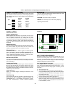
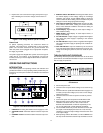
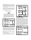
For auto-parallel operation of two supplies, the combined output
volta
g
e is the same as the master unit's volta
g
e settin
g
, and the
combined output current is two times the master unit's current. In
g
eneral, for two supplies, the auto-parallel output current(Io) is
Io = Im + Is = 2Im
where Im = master unit's output current
Is = slave unit's output current
Proportional currents from auto-paralleled units require
equal load-lead volta
g
e drops. Connect each suppl
y
to
the load usin
g
separate pairs of wire with len
g
th chosen
to provide equal volta
g
e drops from pair to pair. If this is
not feasible, connect each suppl
y
to a pair of distribution
terminals usin
g
equal- volta
g
e-drop wire pairs, and then
connect the distribution terminals to the load with a sin
g
le
pair of leads.
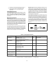
Fi
g
ure 9. Auto-Parallel Operation of Two Supplies
Overvolta
g
e Protection. Adjust the desired OVP shutdown limit
usin
g
the master unit's OVP Adjust control. Set the slave units'
OVP limits above the master's. When a master-unit shuts down,
the master pro
g
rams the slave units to zero volta
g
e output. If a
slave unit shuts down, it shuts onl
y
itself down. If the required cur-
rent is
g
reat enou
g
h, the master will switch from CV to CC opera-
tion.
Remote Sensin
g
. To remote sense with auto-parallel operation,
connect remote-sense leads onl
y
to the master unit accordin
g
to
the remote-sensin
g
instructions.
Remote Analo
g
Volta
g
e Pro
g
rammin
g
. To remote pro
g
ram with
auto-parallel operation, set up onl
y
the master unit for remote pro-
g
rammin
g
accordin
g
to the remote-pro
g
rammin
g
instructions.
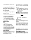
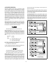
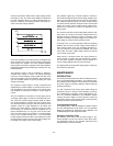
Fi
g
ure 10. Auto-Parallel Operation of Three Supplies
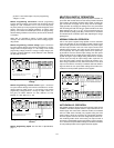
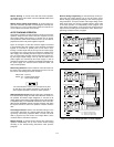
NORMAL SERIES OPERATION
Series operation of two or more power supplies can be accom-
plished up to the output isolation ratin
g
of an
y
one suppl
y
to
obtain a hi
g
her volta
g
e than that available from a sin
g
le suppl
y
.
Series connected supplies can be operated with one load across
both supplies or with a separate load for each suppl
y
. These
power supplies have a reverse polarit
y
diode connected across
the output terminals so that if operated in series with other sup-
plies, dama
g
e will not occur if the load is short-circuited or if one
suppl
y
is turned on separatel
y
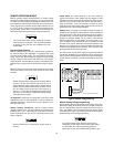
from its series partners. When this
connection is used, the output volta
g
e is the sum of the volta
g
es
of the individual supplies. Each of the individual supplies must be
adjusted in order to obtain the total output volta
g
e. Fi
g
ure 11
shows the rear panel switch settin
g
s and terminal connections for
normal series operation of two supplies.
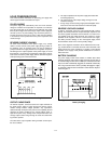
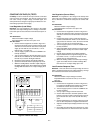
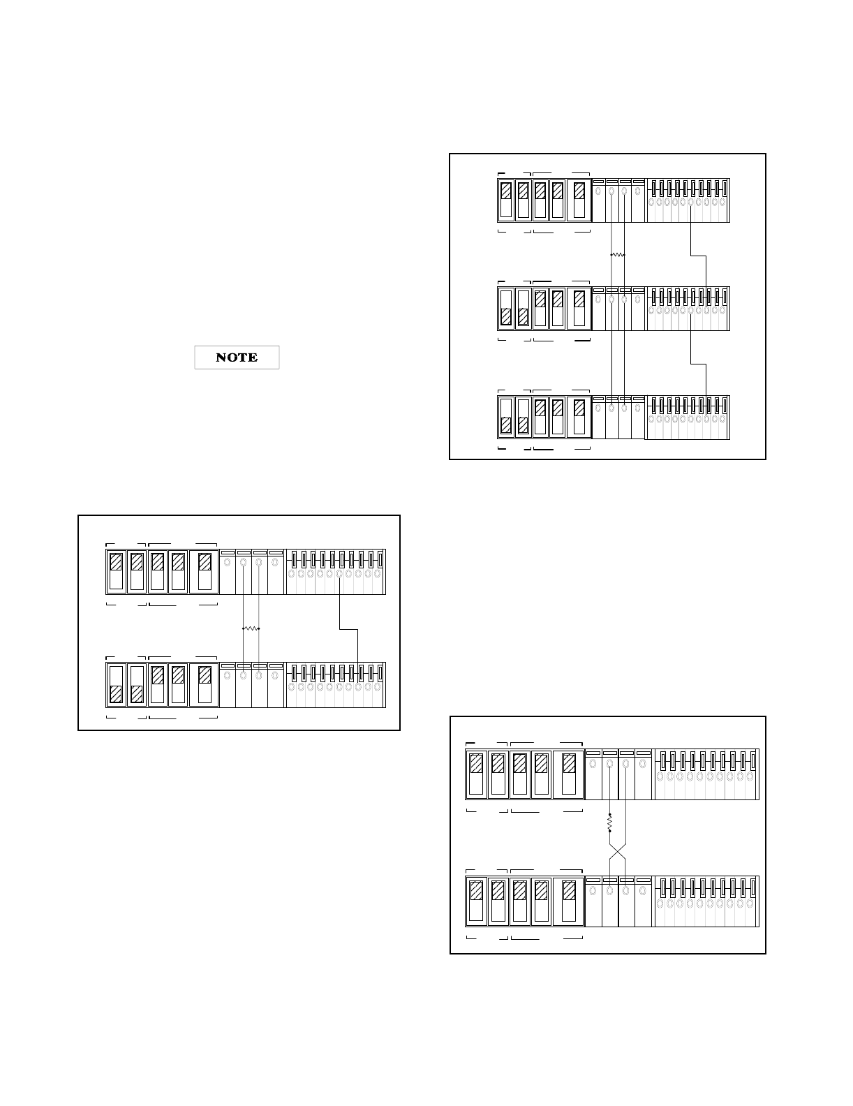
Fi
g
ure 11. Normal Series Operation of Two Supplies
MASTER
SLAVE
CV CC SENSE
LOCAL
REMOTE
OUT
+S
-S
+
_
CV CC
VREF
A1 A2 A3 A4 A5
+
+
M/S 1 M/S 2
__
MASTER
SLAVE
CV CC SENSE
LOCAL
REMOTE
OUT
+S
-S
+
_
CV CC
VREF
A1 A2 A3 A4 A5
+
+
M/S 1 M/S 2
_
_
MASTER POWER SUPPLY
LOAD
SLAVE POWER SUPPLY
MASTER
SLAVE
CV CC SENSE
LOCAL
REMOTE
OUT
+S
-S
+
_
CV CC
VREF
A1 A2 A3 A4 A5
+
+
M/S 1 M/S 2
__
MASTER POWER SUPPLY
LOAD
MASTER
SLAVE
CV CC SENSE
LOCAL
REMOTE
OUT
+S -S
+
_
CV CC VREF A1 A2 A3 A4 A5
+
+
M/S 1 M/S 2
__
SLAVE POWER SUPPLY
MASTER
SLAVE
CV CC SENSE
LOCAL
REMOTE
OUT
+S
-S
+
_
CV CC
VREF
A1 A2 A3 A4 A5
+
+
M/S 1 M/S 2
__
SLAVE POWER SUPPLY
MASTER
SLAVE
CV CC SENSE
LOCAL
REMOTE
OUT
+S -S
+
_
CV CC
VREF
A1 A2 A3 A4 A5
+
+
M/S 1 M/S 2
__
MASTER
SLAVE
CV CC SENSE
LOCAL
REMOTE
OUT
+S
-S
+
_
CV CC
VREF
A1 A2 A3 A4 A5
+
+
M/S 1 M/S 2
_
_
POWER SUPPLY
POWER SUPPLY
LOAD