


1-7
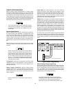
e.Replace the cover and mark the supply clearly with a tag or
label indicating the correct line voltage and fuse that is in
use.
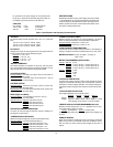
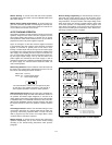
Figure 2. Line Voltage Selector (set for 115 Vac)
Power Cord
To protect operating personnel, the instrument should be
grounded. This instrument is equipped with a three conductor
power cord. The third conductor is the ground conductor and
when the power cord is plugged into an appropriate receptacle,
the supply is grounded.
The power supply was shipped with a power cord for the type of
outlet used at your location. If the appropriate cord was not
included, contact your nearest Agilent Sales Office to obtain the
correct cord.
OPERATING INSTRUCTIONS
INTRODUCTION
This section explains the operating controls and indicators and
provides information on many operating modes possible with your
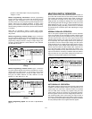
instrument. The front panel controls and indicators are illustrated
in Figure 3.
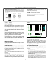
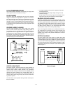
Figure 3. Front-Panel Controls and Indicators
1.
LINE Switch:
Pressing this switch turns the supply on, or off.
2.
VOLTAGE Control:
Clockwise rotation increases output volt-
age.
3.
CURRENT Control:
Clockwise rotation increases output cur-
rent.
4.DISPLAY OVP/CC SET Switch: Pressing this switch causes
the VOLTS display to show voltage setting for overvoltage
shutdown (trip voltage) and the AMPS display to show the
current control set value. Setting values are either front panel
settings or remote voltage programmed settings.
5.
OVP Adjust Screwdriver Control:
While pressing the DIS-
PLAY OVP/CC SET switch, rotating the control clock-wise
with a small, flat-blade screwdriver increases the setting for
overvoltage shutdown.
6.VOLTS Displa
y: Di
gital display of actual output voltage, or
OVP shutdown setting.
7.
AMPS Display:
Digital display of actual output current, or
output-current setting.
8.CV LED Indicator: Output voltage is regulated when lighted.
This means the power supply is operating in the constant
voltage mode.
9.CC LED Indicator: Output current is regulated when lighted.
This means the power supply is operating in the constant cur-
rent mode.
10.OVP LED Indicator: Output is shutdown by the occurrence
of an overvoltage when lighted. Removing the cause of over-
voltage and turning the power off, then on, resets the power
supply.
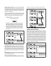
TURN-ON CHECKOUT PROCEDURE
The following checkout procedure describes the use of the front
panel controls and indicators illustrated in Figure 3 and ensures
that the supply is operational:
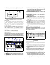
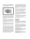
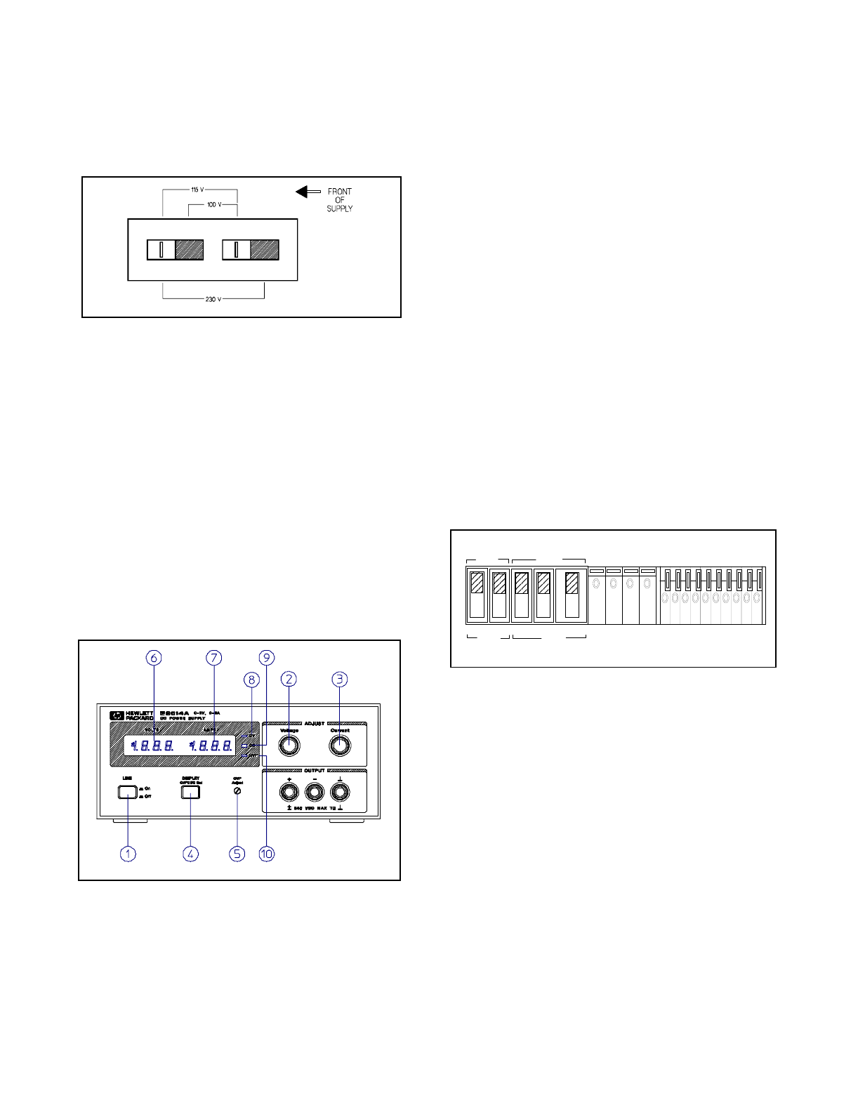
Figure 4. Switch Settings of Rear-Panel Control for Turn-
On Checkout
a.Disconnect power cord.
b.Check that the rear-panel switch settings are as shown in Fig-
ure 4.
c. Check that the rear panel label indicates that the supply is set
to match your input line voltage (If not, refer to "Line Voltage
Option Conversion".).
d.Check that the fuse on the rear panel is correct for your line
voltage.
e.Connect the power cord and push the LINE switch to ON.
f. While pressing OVP/CC SET switch, verify that the OVP
shutdown is set above 8.0, 20.0, 35.0, or 60.0 Vdc for
E3614A, E3615A, E3616A, or E3617A respectively. If not,
turn up OVP Adjust with a small flat-blade screwdriver.
g.Turn VOLTAGE control fully counter clockwise to ensure that
the output of VOLTS display decreases to 0 Vdc, then fully
clockwise to ensure that output voltage increases to the maxi-
mum output voltage.
h.While pressing OVP/CC SET switch, turn the CURRENT con-
trol fully counter clockwise and then fully clockwise to ensure
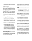
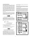
MASTER
SLAVE
CV CC SENSE
LOCAL
REMOTE
OUT
+S
-S
+
_
CV CC
VREF
A1 A2 A3 A4A5
+
+
M/S 1 M/S 2
__