


A-2
series pass transistors. Whenever the output volta
g
e is below
the slopin
g
V1 line, the control circuit inhibits four SCRs and
the input capacitors char
g
e to a volta
g
e determined b
y
N1.
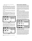
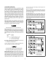
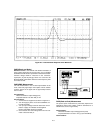
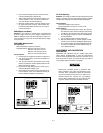
Fi
g
ure A-2 indicates the windin
g
s that are connected as a
result of the other volta
g
e decisions.
Fi
g
ure A-2. Output Power Plot
The series re
g
ulators (Q1 and Q4) are part of a feedback loop
which consists of the driver and the Constant Volta
g
e/Con-
stant Current error amplifier. The series re
g
ulator feedback
loop provides "fine and fast" re
g
ulation of the output while the
prere
g
ulator feedback loop handles lar
g
e, relativel
y
slow, re
g
-
ulation demands.
The re
g
ulator is made to alter its conduction to maintain a
constant output volta
g
e or current. The volta
g
e developed
across the current samplin
g
resistors (R58 and R59) is the
input to the constant current error amplifier. The constant volt-
a
g
e error amplifier obtains its input b
y
samplin
g
the output
volta
g
e of the suppl
y
.
An
y
chan
g
es in output volta
g
e or current are detected and
amplified b
y
the constant volta
g
e or constant current error cir-
cuit and applied to the series re
g
ulator in the correct phase
and amplitude to counteract the chan
g
e in output volta
g
e or
current.
Two error amplifiers are included in a CV/CC suppl
y
, one for
controllin
g
output volta
g
e, the other for controllin
g
output cur-
rent. Since the constant volta
g
e amplifier tends to achieve
zero output impedance and alters the output current when-
ever the load resistance chan
g
es, while the constant current
amplifier causes the output impedance to be infinite and
chan
g
es the output volta
g
e in response to an
y
load resis-
tance chan
g
e, it is obvious that the two amplifiers can not
operate simultaneousl
y
. For an
y
g
iven value of load resis-
tance, the power suppl
y
must act either as a constant volta
g
e
source or as a constant current source - it can not be both;
transfer between these two modes is accomplished at a value
of load resistance equal to the ratio of the output volta
g
e con-
trol settin
g
to the output current control settin
g
.
Full protection a
g
ainst an
y
overload condition is inherent in
the Constant Volta
g
e/Constant Current desi
g
n principle since
there is not an
y
load condition that can cause an output which
lies outside the operatin
g
re
g
ion. For either constant volta
g
e
or constant current operation, the proper choice of front panel
volta
g
e and current control settin
g
s insures optimum pro-
tection for the load device as well as full protection for the
power suppl
y
.
The reference and bias circuit provides stable reference volt-
a
g
es which are used b
y
the constant volta
g
e/current error
amplifier circuits for comparison purpose. The displa
y
circuit
provides an indication of output volta
g
e and current for con-
stant volta
g
e or constant current operatin
g
modes.
An operator error or a component failure within the re
g
ulatin
g
feedback loop can drive a power suppl
y
's output volta
g
e to
man
y
times its preset value. The overvolta
g
e protection cir-
cuit is to protect the load a
g
ainst this possibilit
y
. The circuit
insures that the power suppl
y
volta
g
e across the load will
never exceed a preset limit.
Diode CR19 is connected across the output terminals in
reverse polarit
y
. It protects the output electrol
y
tic capacitor
and the series re
g
ulator transistors from the effects of a
reverse volta
g
e applied across the output terminals.
The displa
y
power circuit provides volta
g
e which is used b
y
A/
D converter and LED drive.
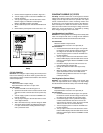
MAINTENANCE
INTRODUCTION
This section provides performance test and calibration proce-
dures and troubleshootin
g
information. The followin
g
opera-
tion verification tests comprise a short procedure to verif
y
that
the power suppl
y
is performin
g
properl
y
, without testin
g
all
specified parameters.
If a fault is detected in the power suppl
y
while makin
g
the
performance check or durin
g
normal operation, proceed to
the troubleshootin
g
procedures. After troubleshootin
g
, per-
form an
y
necessar
y
adjustments and calibrations. Before
returnin
g
the power suppl
y
to normal operation, repeat the
performance check to ensure that the fault has been properl
y
corrected and that no other faults exist.
Test Equipment Required
The followin
g
Table A-1 lists the equipment required to perform
the tests and adjustments of this section. You can separatel
y
identif
y
the equipment for performance tests, calibration, and
troubleshootin
g
in the USE column of the table.
Operation Verification Tests
The followin
g
tests assure that the power suppl
y
is per-
formin
g
properl
y
. The
y
do not, however, check all the speci-
fied parameters tested in the complete performance test
described below. Proceed as follows: