


Programming in PCL
CNT-APG002-EN 25
®
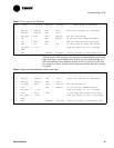
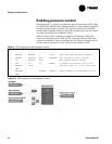
Table 8 shows a PCL program with separated enable/disable and fail-safe
logic. The logic is separated because in this case the enable/disable and
fail-safe conditions have different results. In line 4, if the fan is off, then
the actuator is closed. In line 6, if the input sensor fails, then the actuator
is opened.
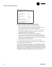
Table 7: PCL program for PID loops
Line Result 1st Arg Operator 2nd Arg Description of Statement
---- -------- --------- -------- --------- ---------------------------------
1 CALC_SP = ROOM_SP MIN *80.0 Check that setpoint is reasonable
2 CALC_SP = CALC_SP MAX *65.0
3 PID_CALC = AIP1 DDC:1 CALC_SP Run PID calculation
4 *L1 = NOT FAN_ON Is the fan off? (Enable/disable)
5 *L2 = AIP1 FAIL Has the input failed? (Fail-safe)
6 *IFT = *L1 OR *L2 If fan is off or input has failed
7 PID_CALC = *-10.0 then set output to -10.0 (closed)
8*END =
9 AOP1 = CONTROL PID_CALC Control actuator to calculated value
Table 8: Separate enable/disable and fail-safe logic
Line Result 1st Arg Operator 2nd Arg Description of Statement
---- -------- --------- -------- -------- -------------------------------------
1 CALC_SP = ROOM_SP MIN *80.0 Check that setpoint is reasonable
2 CALC_SP = CALC_SP MAX *65.0
3 PID_CALC = AIP1 DDC:1 CALC_SP Run PID calculation
4 *IFT = NOT FAN_ON If the fan off (Enable/disable)
5 PID_CALC = *-10.0 then set output to -10.0 (closed)
6 *IFT = AIP1 FAIL If the input has failed (Fail-safe)
7 PID_CALC = *100.0 then set output to 100.0 (fully open)
8 *END =
9 AOP1 = CONTROL PID_CALC Control actuator to calculated value